8 Connection FLUXUS WW
UMFLUXUS_WWV1-1EN, 2018-02-28 55
8.1.3 Connection of the extension cable to the junction box
8.1.3.1 Connection without potential separation (standard)
The connection of the extension cable to the junction box without potential separation ensures that transducer, junction
box and transmitter are on the same potential. The extension cable should always be connected in this manner, especially
if power current cables are nearby the extension cable.
If earthing on the same potential cannot be ensured (see section 8.1.3.2).
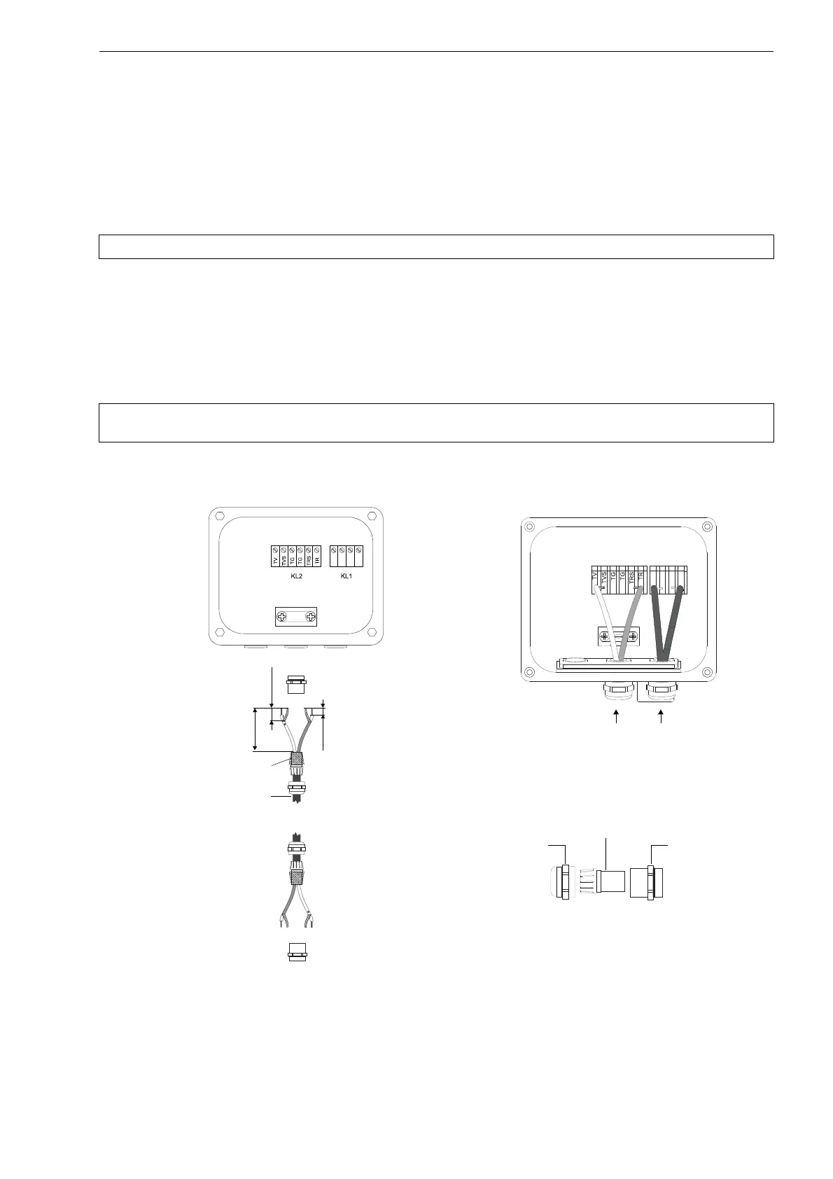
• Remove the left blind plug for the connection of extension cable (see Fig. 8.6).
• Open the cable gland of the extension cable. The compression part remains in the cap nut.
• Push the extension cable through the cap nut and the compression part.
• Prepare the extension cable.
• Shorten the external shield and brush it back over the compression part.
• Screw the sealing ring side of the basic part tightly into the junction box.
• Insert the extension cable into the junction box.
• Fix the cable gland by screwing the cap nut onto the basic part.
• Connect the extension cable to the terminals of the junction box (see Fig. 8.6 and Tab. 8.5).
Attention! Observe the "Safety instructions for the use in explosive atmospheres" (see SIFLUXUS document).
Attention! For good high frequency shielding, it is important to ensure good electrical contact between the exter-
nal shield and the cap nut (and thus to the junction box).
Fig. 8.6: Connection of the extension and transducer cable to the junction box JBxx
100 mm
20 mm
10 mm
extension cable
extension cable transducer cable
cap nut
compression part
basic part
cable gland
external shield,
brushed back