System Description
432-0012-00-10 Version 100 December 2015 10
M400 Components:
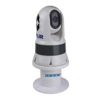
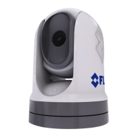
• Main camera body, also known as the pan/tilt camera unit
• Joystick Control Unit (JCU II), compatible with the MU, MV, and M400 camera systems
• Ethernet switch with power over Ethernet (PoE) to power the JCU II and network to the camera
• Analog and/or digital video monitors (customer supplied)
• Personal computer (PC) to control and configure the system (customer supplied)
The M400 camera body and JCU II are network devices. In some installations, additional M400
cameras and/or additional JCU II may also be used.
The camera body’s pan/tilt mechanism allows the operator to rotate 360° in azimuth, tilt +/– 90° in
elevation. The camera body houses the two cameras and the LED spotlight.
The JCU II is the primary control for the camera. The JCU II is used to wake the system or put it in
standby, select the active camera, operate the pan and tilt movement of the camera, zoom the
active camera, control the M400 modes and features, and configure the system settings by means
of OSD menus.
The JCU II has various buttons, an LCD display, and the joystick. The joystick can be moved left
and right or forward and back, and rotated in either direction. “M400 Joystick Control Unit” on
page 16 describes the functions of the JCU II in detail.
The M400 uses on-screen icons to indicate the camera position (azimuth and elevation) and
various system settings that have been enabled. These symbols are introduced in “Thermal Video
Display” on page 11 and are further explained throughout this manual in the discussion of related
functions.
Multiple Cameras, Joysticks, and Other Devices:
More than one JCU II can be used to control the camera, and more than one display can be used
to view the video. A personal computer (PC) on the same network as the camera, can use a web
browser to view video, control, and configure the system. The camera’s web server uses password
protected accounts to control access to camera functions. Using a PC is described in “IP Interface
and PC Operations” on page 30.
Also, a single JCU II can be used to select and control more than one camera. In this case, a
menu on the JCU II lists available cameras. In the LCD display of the JCU II, the name of the
currently selected camera is displayed. When more than one JCU II is installed in the network, a
camera will respond to commands from any JCU II that has the camera selected.
Typically, a JCU II and a video monitor are mounted in close physical proximity, as a pair, so you
can immediately see the changes on the video screen when you use the JCU II to change the
camera position (pan or tilt).
Contact FLIR Systems, Inc. for more information regarding available accessories including PoE
equipment, video distribution amplifiers, cables, connectors, mounting hardware, etc. Contact
information is listed on the back of this manual.