M400 Web Browser Interface
432-0012-00-10 Version 100 December 2015 37
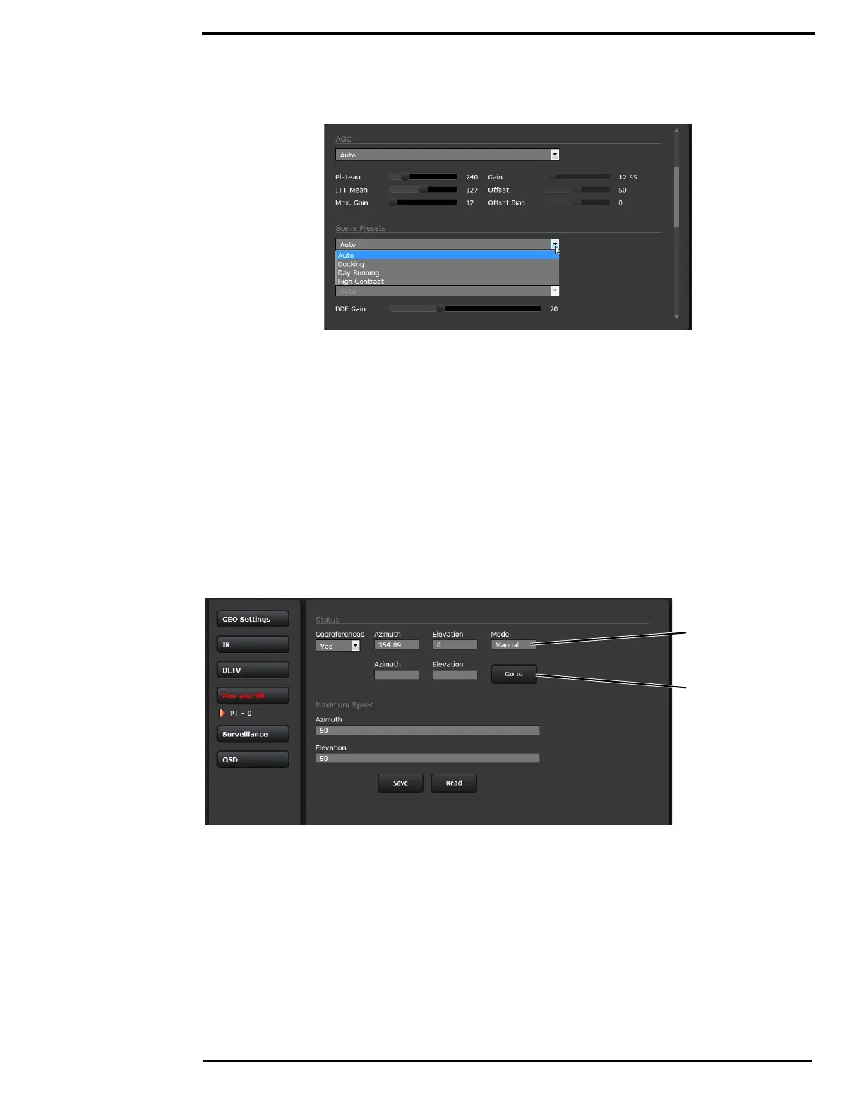
Setup->IR->AGC Scene Presets
The AGC parameters affect how the overall video image appears. The default Auto algorithm is
suitable for most installations, but in some cases one of the other selections may provide a more
appealing image, depending on personal preferences. Be aware the settings that are optimal at
one time may be less optimal a short time later, since conditions such as weather and time of day
affect the image and are constantly changing.
It may be best to start with the Scene Presets selections, but experiment with different AGC
settings. It is always possible to return to the default settings by selecting the Factory Defaults
button at the bottom of the page.
Each Scene Preset provides a combination of AGC and Digital Detail Enhancement (DDE)
parameters that are preferred for certain types of conditions. Select a preset that provides an
image that is optimal for the situation. DDE can be thought of as sharpness, higher values
increase sharpness, while lower values soften (blur) the image and filter fixed pattern noise.
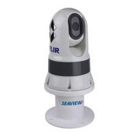
Setup->Pan and Tilt->Status
Icons on the video show the direction the camera is facing in relation to an outline of a ship. The
Pan and Tilt status shows the azimuth and elevation of the current direction of the camera.
The azimuth angle is measured from 0 to 360 starting to starboard from the bow of the ship outline
icon on the video. The elevation angle is measured from horizontal; minus values are down.
positive values are up. Both the reported angles and the Go to angles take into consideration the
Offsets. See “Azimuth and Elevation Offsets” on page 44.
The Azimuth “0” direction should be directly toward the front of the vessel; the elevation may be
set to the horizon or another preferred reference. The azimuth and elevation offsets are set using
the OSD menu. Refer to “Set Az & El zero reference:” on page 26.
To move the camera
enter coordinates,
click Go to.
Reported direction
coordinates, updated
in real time.