Thermal Video Display
432-0012-00-10 Version 100 December 2015 11
Thermal Video Display
The infrared (IR) imaging thermal camera relies on the fact that all objects, even very cold objects
like ice, emit thermal energy in the portion of the infrared spectrum that the camera can see.
Therefore, unlike an illuminated infrared camera, the thermal imaging camera does not need an
additional active illumination source and images are based on directly radiated energy rather than
reflected energy.
When the thermal camera is in white-hot mode, the warm objects in the scene are shown as white,
or lighter shades of gray, and cold objects are shown as black or darker shades of gray. When the
video polarity is switched, this is reversed.
This is why hot objects such as parts on a running outboard motor appear white (or black or red
depending on the video image mode selected), while the water or other cold objects appear dark
(or cool). Scenes with familiar objects will be easy to interpret with some experience. The camera
automatically optimizes the image to provide the best contrast in most conditions.
FLIR Systems, Inc. offers a comprehensive selection of training courses to help you to get the best
performance and value from your thermal camera. Find out more at the FLIR training Web page:
http://www.flir.com/training
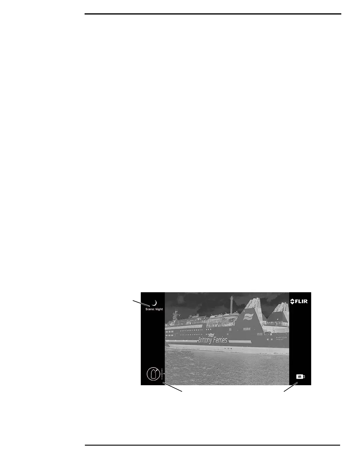
Video Screen Icons
Depending on the system settings, various symbols are shown on the screen. Some of these icons
are always shown on the screen, and some appear momentarily or only when certain functions are
enabled or executed. The icons can be shown as white or red. See “Display icons:” on page 24 for
a description of menu options and the displayed icons.
The following figures illustrate some of the icons displayed by the system, as well as an example
of the OSD menu that is shown when the Menu button is pressed. Using the menus is described in
“M400 System Configuration” on page 20.
A complete list of all of the icons used in the system and a brief description of how they are used
can be found in “List of Icons” on page 54.
Active CameraPosition indicators
Scene type
Figure 1-2: On-screen Icons