List of Icons
432-0012-00-10 Version 100 December 2015 54
List of Icons
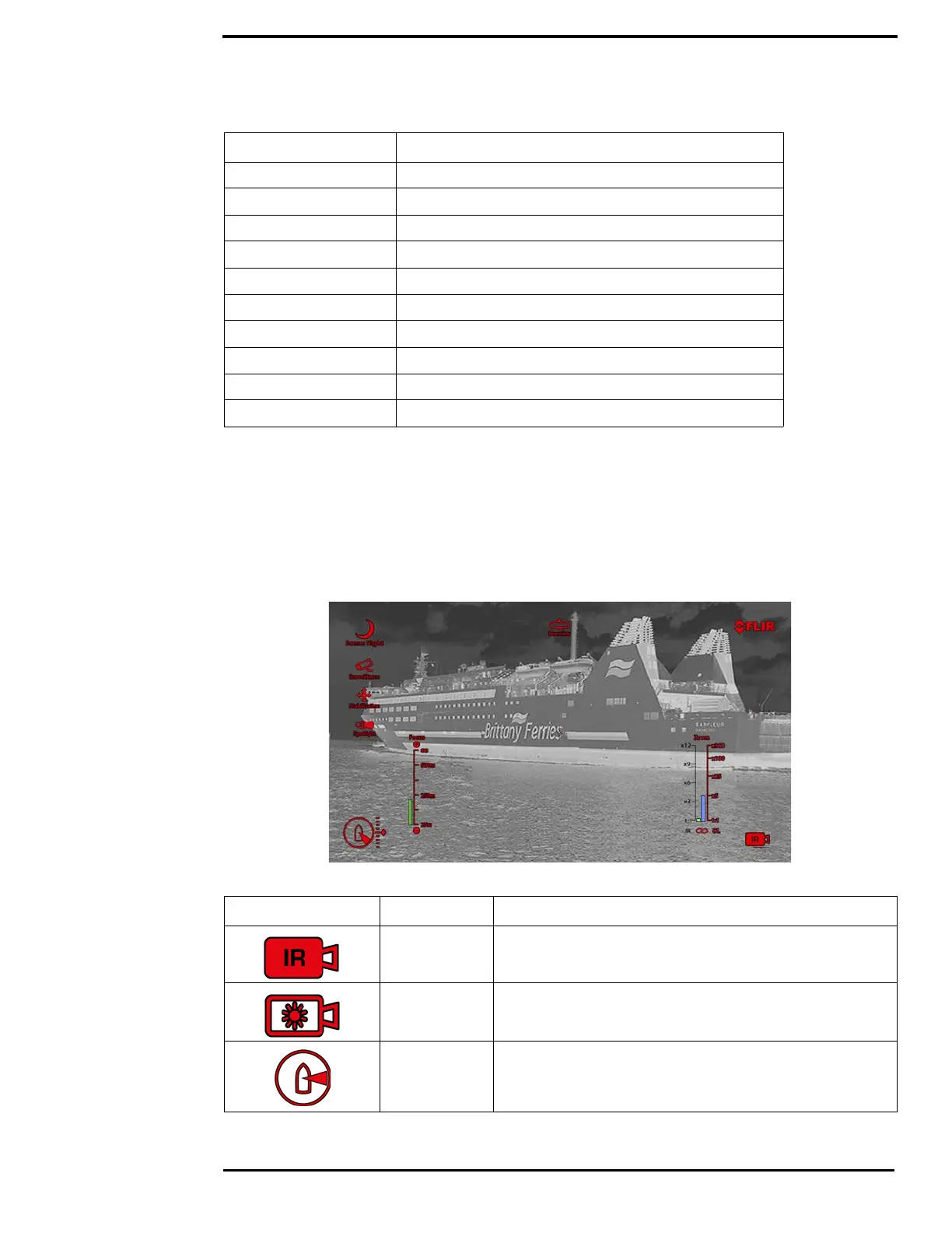
Table 6.2 lists the icons that may be shown on the screen during various operations, with a brief
description of their meaning. Some icons display permanently and some only display briefly. The
display of some icons is affected by settings on the Display Icons menu (see page 24).
NTSC National Television System Committee
OSD on-screen-display
P/T Pan/Tilt
PAL Phase Alternating Line
PoE Power over Ethernet
SCTE Society of Cable Telecommunications Engineers
SDK Software Developer’s Kit
UPnP Universal Plug and Play
Vdc Volts, Direct Current
VIS Visible (visible-band camera reference)
TABLE 6.2 Video Display Icons
Icon Name Description
Thermal
camera
Daylight
camera
Azimuth
(Position)
Shows the azimuth (or direction) of the camera relative to the
vessel. The shaded triangle shows the approximate camera
field of view (FOV).
TABLE 6.1 Acronyms
Acronym/Term Definition