Page 52CWT Compact S4 Touch Installation & Maintenance Manual for CWT 1.0-0Issue 3
Installation
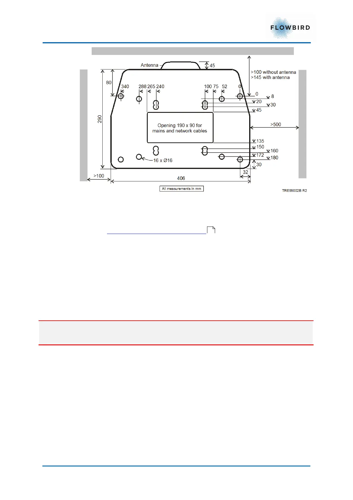
Figure 35, Terminal installation drawing
The above figure shows all the alternative mounting holes in the pedestals bottom
plate. See Pouring a new concrete foundation regarding placing the terminal
on a base anchor cast into a foundation.
A cable for connection to the power grid is drawn through the floor (from the floor
below, for example) and into the pedestal through the opening in the mounting
frame (optional). Alternatively, a hole can be drilled in the pedestal and the cables
drawn in some other way. The cable must be protected against damage. Use
proper cable bushing to prevent cable wear and moisture entry into the pedestal.
Danger:
Follow local regulations regarding electrical installations.
5.1.2
Solar power positioning
The ideal installation of the terminal may vary due to the surroundings. A thumb
rule is to have the solar panel facing south with the panel surface perpendicular
towards the sun.
The drawing below illustrates how a Flowbird terminal is installed on an undefined
street with obstacles (buildings) on both sides. The illustration also shows the
angle where the solar panel will get the most sun during the day. Please note that
the angle is also 360 degrees around the terminal. Mentioned parameters must be
considered when planning an installation.
54