Page 53CWT Compact S4 Touch Installation & Maintenance Manual for CWT 1.0-0Issue 3
Installation
Also, note that different latitudes will give variances in optimal solar angles, which
also affects the ideal positioning of the terminal.
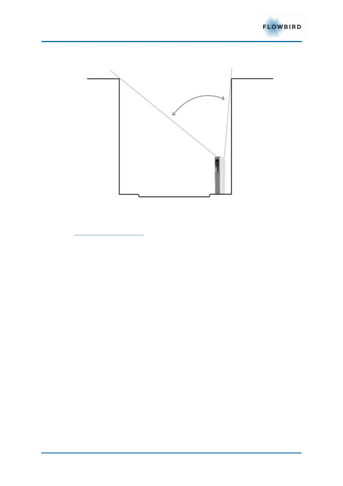
Figure 36, Solar Panel Placement.
Obstacles and shading
Even the smallest shading of the solar panel will result in substantial loss of output
power. If, for example, 2% of the surface of the solar panel were to be shaded, the
output efficiency would be 30% lower due to serial connection between the solar
cells.
Shading can be caused by many different things, such as trees, buildings,
balconies, dirt/debris, and snow. The risk of shading from buildings and other
objects in the vicinity will increase during the winter due to the lower altitude of the
sun.
5.1.3
Placing the terminal on an existing concrete
foundation
The pedestal is attached directly to the foundation using 4–8 expansion bolts, see
Figure below. The maximum bolt diameter is 12 mm.
The bottom plate extends 1.5 mm below the housing of the pedestal and you can
place the pedestal directly on top of the foundation without any risk of damaging
the housing.