- 11 -
While the optimum values for each of these factors for a given application is usually determined through
application development, a “starting point” is easily determined merely by looking at the particle size
range under study.
Electronics
The Digital Signal Processor (DSP) and trigger circuitry are central to the
operation of the instrument. They provide a critical interface between the
software and all other components of the FlowCAM. This complex circuit
board measures the parameters of the fluorescence and/or light scatter signals
and provides these parameters to the processor upon request. It also provides
trigger signals which are generated when passing particles are of sufficient
fluorescence or within previously set light scatter parameters. While in
AutoImage mode, this board generates the appropriate signals to the camera
and image processor.
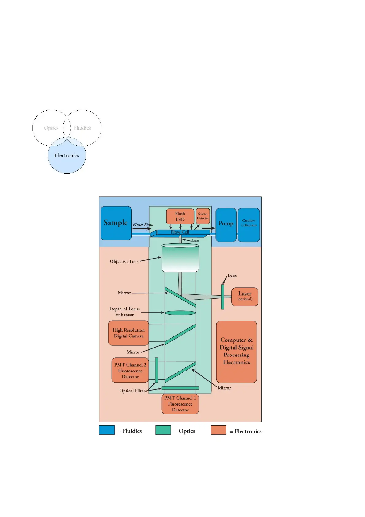
Figure 1. FlowCAM Block Diagram