Fluke 434-II/435-II/437-II
Users Manual
5-2
Phase Colors
Measuring results belonging to different phases are presented with individual colors. If -
for a certain phase - voltage and current are displayed simultaneously, the voltage color
has a dark tone and the current has a light tone.
The set of phase colors can be chosen via the SETUP key and function key F1 – USER
PREF. Then select Phase Colors with the up/down arrow keys. Next press ENTER to
reach the menu. Within the menu use the up/down arrow keys to choose the desired
colors and confirm with the ENTER. For detailed information see Chapter 24.
Screen Types
Below you will find a brief description of each screen type and its purpose. The
measuring mode it is used for is given as well as the manual chapter (Ch.) with detailed
information. Bear in mind that the amount of screen information depends on the number
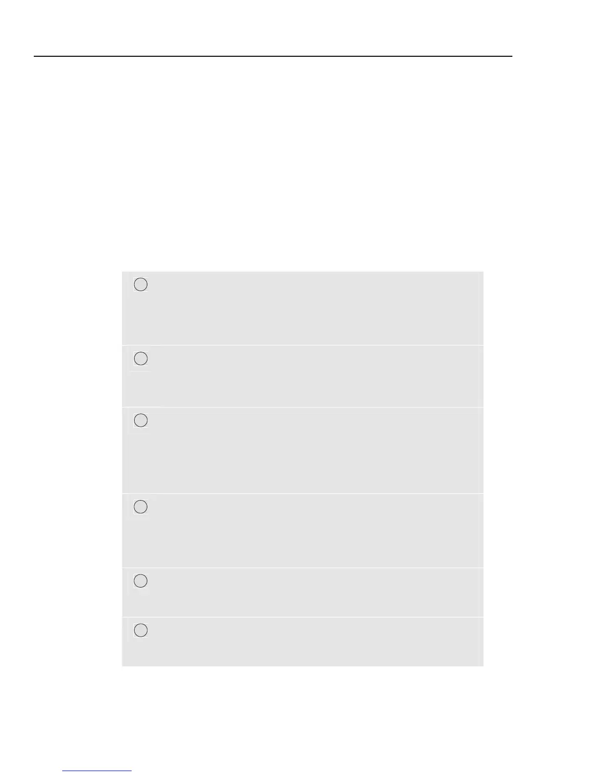
of phases and the wiring configuration. Refer to Figure 5-1, item 1 ... 6.
1
Meter screen: gives an instantaneous overview of a big number of
important numerical measuring values. All these values are logged as
long as the measurement is on. They are stored in memory when the
measurement is stopped. Used for all measurements except Monitor
(Ch. 16) and Power Wave (Ch. 19).
2
Trend screen: this type of screen is related to a Meter screen. Trend
shows the course over time of measuring values from the Meter screen.
After selection of a measuring mode, the Analyzer starts recording all
readings in the Meter screen. Used for all measurements.
3
Waveform screen: shows voltage and current waveforms as displayed
on an oscilloscope. Channel A (L1) is reference channel and 4 complete
cycles are displayed. The nominal voltage and frequency determine the
measuring grid size. Used for: Scope Waveform (Ch. 7), Transients
(Ch. 18), Power Wave (Ch. 19), and Wave Event in Fluke 435-II/437-
II.
4
Phasor screen: shows the phase relation between voltages and currents
in a vector diagram. The vector of reference channel A (L1) points to
the positive horizontal direction. The A (L1) amplitude is also reference
for the measuring grid size. Used for: Scope Phasor (Ch. 7) and
Unbalance (Ch. 14).
5
Bar Graph screen: shows the density of each measuring parameter as a
percentage by means of a Bar Graph. Used for: Harmonics (Ch. 10),
and Power Quality Monitor (Ch. 16).
6
Events list: lists the events that occurred during the measurement with
data such as start date/time, phase and duration. Used for all
measurements except Power Wave (Ch. 19).
1.800.868.7495info@Fluke-Direct.ca
Fluke-Direct.ca
 Loading...