6-1
Chapter 6
Input Connections
Introduction
This chapter explains how to make connection to the power distribution system under test
and how to adjust the Analyzer settings.
Check that the Analyzer setup meets the characteristics of the system under test and the
accessories that are used. This concerns:
• wiring configuration
• nominal frequency
• nominal voltage
• limits used for power quality monitor and event detection
• properties of voltage leads and current clamps
For a quick verification of the key elements, use the setup wizard attainable via the
SETUP key and function key F3 – SETUP WIZARD. Refer to Chapter 24 for more
information.
The actual setup is shown in the welcome screen that appears after power up. To change
the setup, refer to Chapter 24.
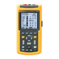
Input Connections
The Analyzer has 4 BNC inputs for current clamps and 5 banana-inputs for voltages.
Note: use only the current clamps as supplied or clamps that are recommended for safe
use with the Analyzer. These clamps have a plastic BNC connector. The use of insulated
BNC connectors is necessary for safe measurements.
Self-adhesive decals are supplied corresponding to wiring color codes used in the USA,
Canada, Continental Europe, the UK, and China. Stick the decals that fit to your local
wiring codes around the current and voltage inputs as shown in Figure 6-1.
1.800.868.7495info@Fluke-Direct.ca
Fluke-Direct.ca
 Loading...