Setting up the Analyzer
MANUAL SETUP24
24-11
f
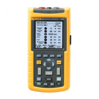
Use the arrow keys to highlight 3φ IT. Then press
ENTER to confirm the selection.
g
ENTER
The diagram shows in detail how to connect
voltage and current probes to the power system
under test.
h
F5
(3x)
Return to Setup entry screen. The new
configuration is indicated behind Config. and the
belonging configuration symbol is shown on the
right side of the screen.
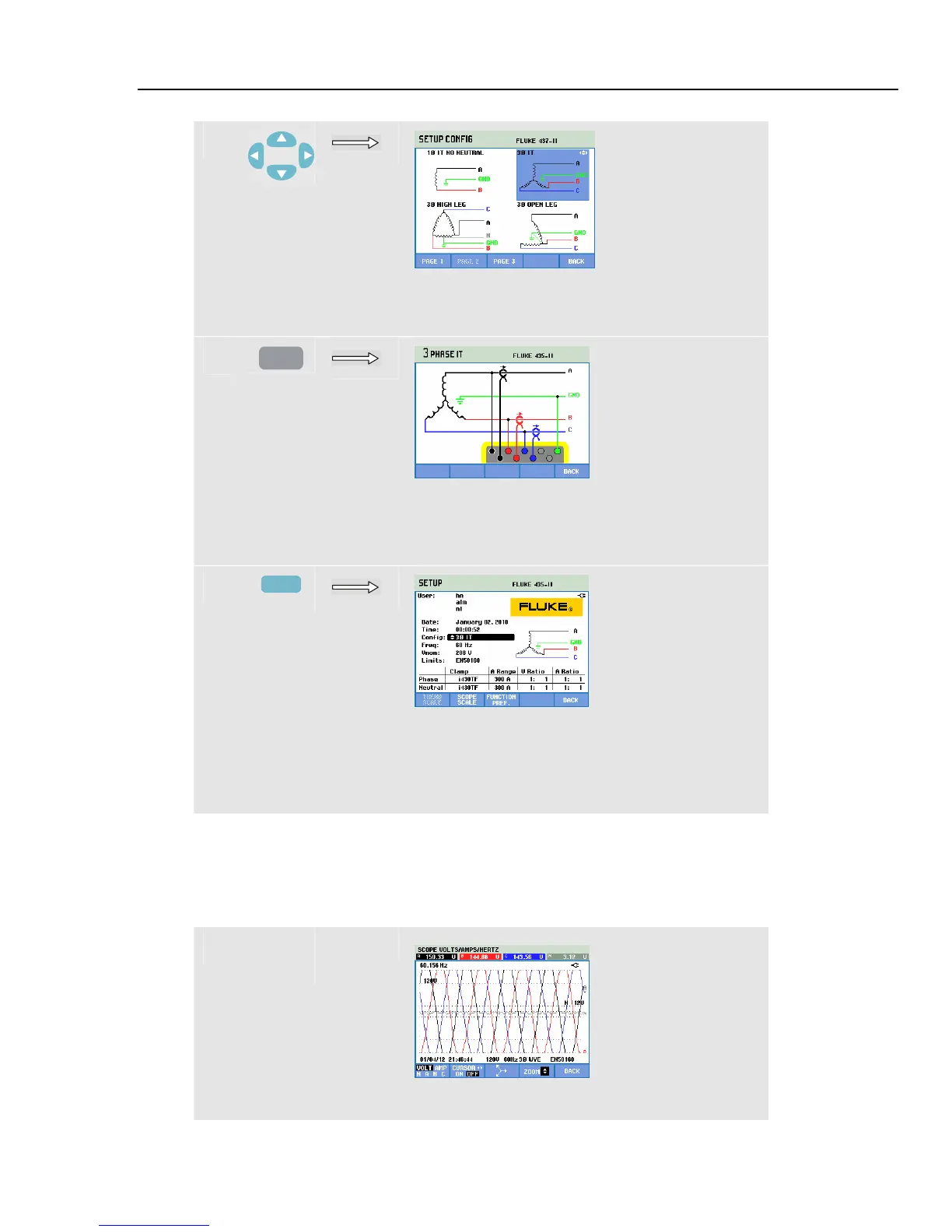
Manual Setup - How to change scale of Scope Display
The example below shows stepwise how to adjust Scope display scaling of the phase
voltages.
c
The voltage waveforms of the Phases are outside
the viewing window.
1.800.868.7495info@Fluke-Direct.ca
Fluke-Direct.ca
 Loading...