Fluke 434-II/435-II/437-II
Users Manual
6-2
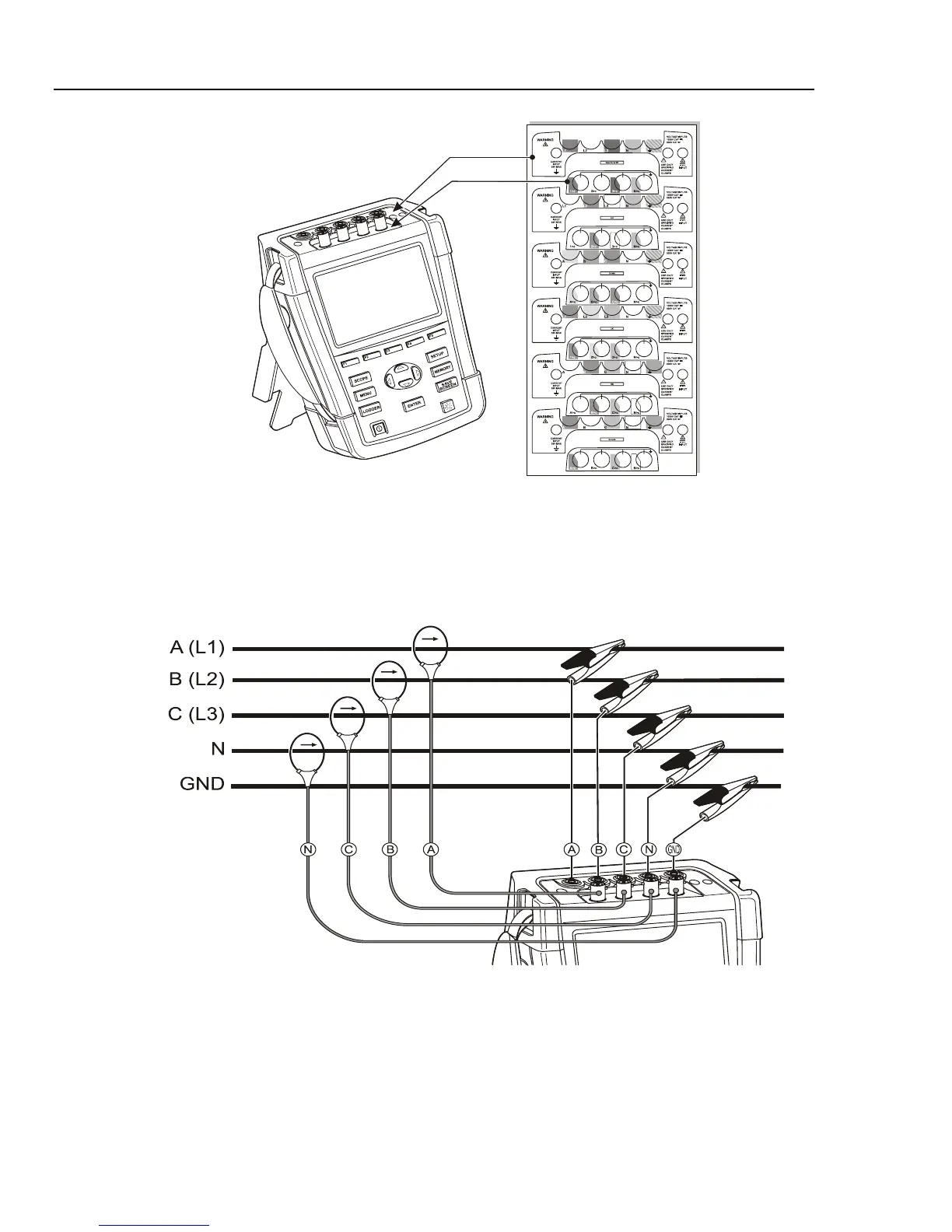
Figure 6-1. Mounting the decals for voltage and current inputs
De-energize power systems before making connections whenever possible. Always use
appropriate equipment for personal protection. Avoid working alone and work according
to the warnings listed in Chapter 1, Safety Information.
For a 3-phase system make the connections as shown in Figure 6-2.
Figure 6-2. Connection of Analyzer to 3-phase distribution system
First put the current clamps around the conductors of phase A (L1), B (L2), C (L3), and
N(eutral). The clamps are marked with an arrow indicating the correct signal polarity.
Next make the voltage connections: start with Ground and then in succession N, A (L1),
B (L2), and C (L3). For correct measuring results, always connect the Ground input.
Always double-check the connections. Make sure that current clamps are secured and
completely closed around the conductors.
1.800.868.7495info@Fluke-Direct.ca
Fluke-Direct.ca
 Loading...