TROUBLESHOOTING AND REPAIR
The system RAM (U6 and U7) is tested by writing data to each memory location and
verifying that the same data can be read back. The RAM test is only done at power-up.
The two program EPROMs (U2 and U3) are tested by verifying their checksums. The
non-volatile RAM is tested by verifying the checksum of each memory location.
Communication with the IEEE-488 interface IC is verified by writing data to the
IEEE-488 talker/listener IC (U28), then reading it back.
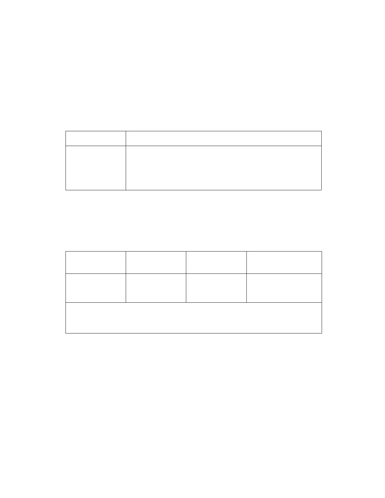
Table 6-3. Digital Test Results
CODE
302
303
304
305
306
DESCRIPTION
Calibration/Compensation memory checksum test failed
RAM test failed
EPROM test failed
Non-volatile memory test failed
IEEE interface test failed
AM Tests 6-25.
The AM Tests program normal and overmodulation conditions and then check the
state of the ALC loop-leveled indicator. Table 6-4 lists the test conditions.
Table 6-4. AM Test Conditions
CODE
307
308
309
AM DEPTH
30.0%
0.0%
>
99.9%
AMPLITUDE
+13.7
dBm
+16.0
dBm
> +20.0 dBm
EXPECTED STATE
OF ALC LOOP
Leveled
Leveled
Unleveled
RF Frequency = 1055 MHz
Mod Frequency = 1 kHz
Internal AM = On
FM Tests 6-26.
The FM Tests program normal and overmodulation conditions and then check the
state of the FM loop-lock indicator. The locked condition is expected in four of the
FM bands and once with the Low-Rate FM mode enabled. The unlocked condition is
expected when a very wide deviation is programmed at a low modulation rate. Table
6-5 lists the test conditions.
øM Tests 6-27.
The Phase Modulation Tests verify that the FM loop remains locked when two valid
phase modulation settings are programmed. The first test is performed at a high
deviation. The second tests is performed with the High-Rate øM mode enabled. Table
6-6 lists the test conditions.
6-9