CLOSED-CASE CALIBRATION
NOTE
The rear panel CAL|COMP switch must be set to the 1 (on) position
before initiating the calibration procedures.
Front Panel Reference Oscillator Calibration Procedure 3-15.
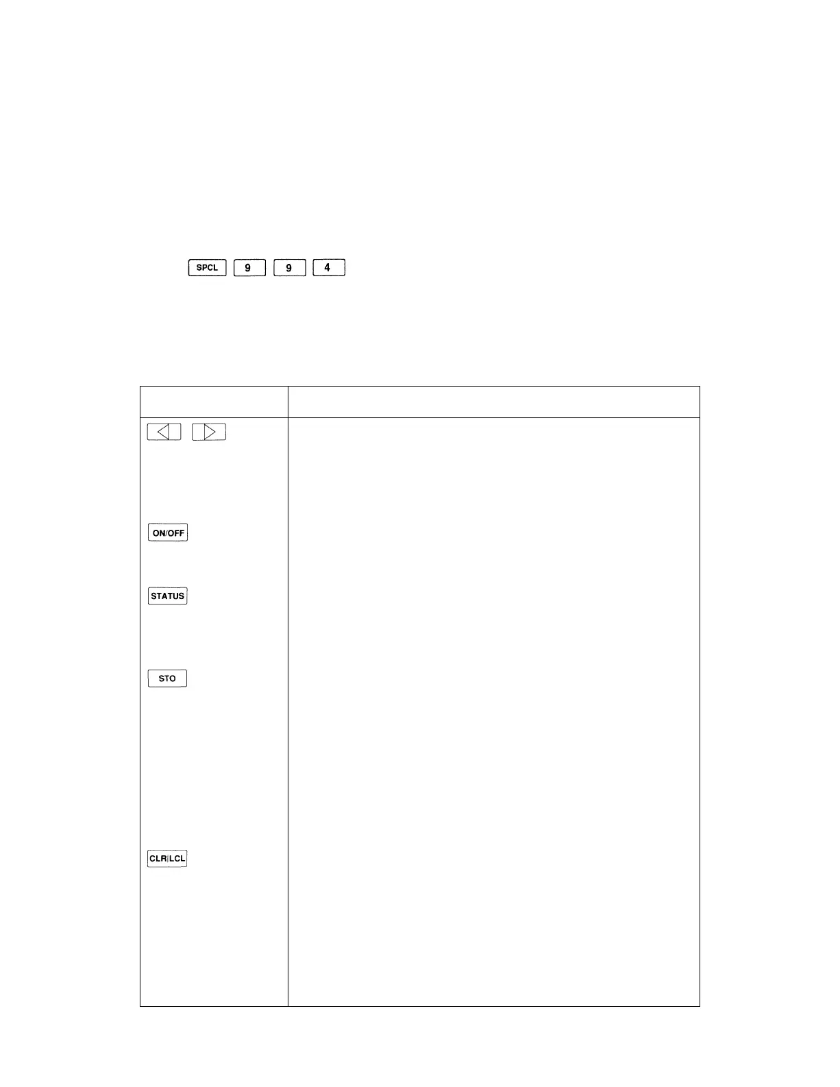
The front panel reference oscillator calibration procedure is initiated by the following
key sequence:
The display is reconfigured for the procedure. Several of the front panel controls are
disabled or operate differently than they normally do. Table 3-7. shows all of the active
controls and describes their function while performing the procedure.
Table 3-7. Front Panel Controls for Reference Oscillator Calibration Procedure
CONTROLS
KNOB
FUNCTION AND DESCRIPTION
Bright-Digit Editing
Turn the edit knob to adjust the reference oscillator calibration factor.
Use the left/right arrow keys to move the bright-digit within the adjust-
ment field. The bright-digit is always located in the adjustment field.
RF on/off
Toggles the RF output on/off.
Overrange/uncal or Rejected Entry Status
Normally displays the overrange/uncal status. Displays the rejected entry
status code if there is a rejected entry.
Store Measured Data
Press once; the prompt "Sto ?" is displayed.
Press again to store the data. The message "— Sto —" is displayed to
confirm the selection. The updated calibration factor is stored in the
calibration memory, and the last valid instrument state is restored.
Press any other key to cancel the store operation and resume the
procedure.
Abort the Cal Procedure
Press once; the prompt "Clr ?" is displayed.
Press again to abort the procedure. The message "— Clr —" is displayed
to confirm the selection. All measured data is discarded and the previous
instrument state is restored.
Press any other key to resume the procedure.
3-15