Endurance
®
Series
Users Manual, Rev. 2.0, Jun 2020
42
6 Operation
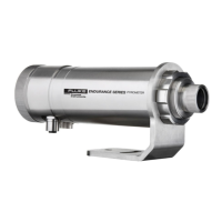
Once the sensor is positioned and connected properly, the system is ready for continuous operation. Nonstop
operation of the Endurance device is achieved either by back panel operation or through software control via the
digital communication interfaces. The Multidrop Software, a MS-Windows based setup and configuration program
is supplied with the sensor. You can also create custom programs using the communication protocols listed in
section 14 ASCII Programming, page 120.
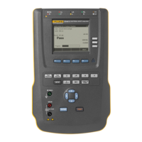
6.1 Control Panel
The Endurance sensor is equipped with a control panel, which is the manually operated user interface and consists
of two display types, a sighting and status indicator, and several control buttons, as shown in the figure below.
The panel is primarily for setting up the instrument prior to nonstop operation. A screw able end cap with a sealed
glass window protects the user interface during nonstop operation.
The sensor has a remote locking feature to protect the unit from accidental interaction over the control panel. This
lockout mode denies access to the submenu functions of the control panel. Via a specific key command over the
control panel or the digital communication the device can be unlocked.
Figure 6-1: Control Panel
 Loading...