14
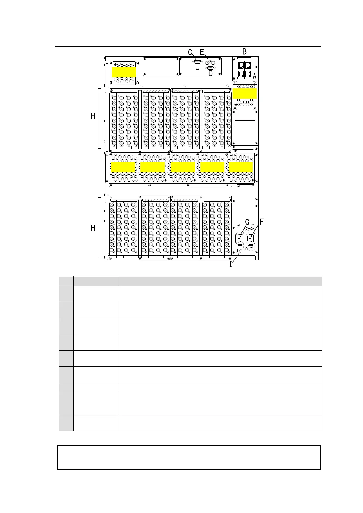
2-2. MFR-6000 Rear Panel
232C 422
SERIAL
REF IN
ALARM
CPU1CPU2
P
C
-
L
A
N
P
C
-
L
A
N
M
F
R
-
L
A
N
M
F
R
-
L
A
N
INPUTOUTPUT
5 6 7 85 6 7 8
OUTPUTINPUT
1 2 3 4 1 2 3 4
INPUT INPUTOUTPUT OUTPUT
A
C
1
0
0
-
2
4
0
V
5
0
/
6
0
H
z
I
N
A
C
1
0
0
-
2
4
0
V
5
0
/
6
0
H
z
I
N
12
13 14 15 1613 14 15 169 10 11 129 10 11 12
1 1 1 1 1 1 1 1 1 1 1 1 1 1 1 1
1 1 1 1 1 1 1 1 1 1 1 1 1 1 1 1
2 2 2 2 2 2 2 2 2 2 2 2 2 2 2 2
2 2 2 2 2 2 2 2 2 2 2 2 2 2 2 2
3 3 3 3 3 3 3 3 3 3 3 3 3 3 3 3
3 3 3 3 3 3 3 3 3 3 3 3 3 3 3 3
4 4 4 4 4 4 4 4 4 4 4 4 4 4 4 4
4 4 4 4 4 4 4 4 4 4 4 4 4 4 4 4
5 5 5 5 5 5 5 5 5 5 5 5 5 5 5 5
5 5 5 5 5 5 5 5 5 5 5 5 5 5 5 5
6 6 6 6 6 6 6 6 6 6 6 6 6 6 6 6
6 6 6 6 6 6 6 6 6 6 6 6 6 6 6 6
7 7 7 7 7 7 7 7 7 7 7 7 7 7 7 7
7 7 7 7 7 7 7 7 7 7 7 7 7 7 7 7
8 8 8 8 8 8 8 8 8 8 8 8 8 8 8 8
8 8 8 8 8 8 8 8 8 8 8 8 8 8 8 8
9 9 9 9 9 9 9 9 9 9 9 9 9 9 9 9
9 9 9 9 9 9 9 9 9 9 9 9 9 9 9 9
*The above figure shows an MFR-6000 with MFR-9SDI12G and MFR-9SDO12G cards installed.
Ethernet ports for connection to MFR Remote Control Units and MFR-GPI
(10/100BASE-TX, RJ-45)
Ethernet ports for connection to PC or other external unit
(10/100/1000BASE-T, RJ-45)
Used for control via a serial interface. RS-232C or RS-422 selectable.
► See Sec. 2-2-1. “Interfaces.”
Used for alarm output
► See Sec. 2-2-1. “Interfaces.”
Used to input reference signals (BB or Tri-level sync signal)
(with loop-through. Terminate with 75Ω terminator, if unused.)
Used to connect Power Supply Unit 1 (standard equipment) to an AC
power source
Used to connect Power Supply Unit 2 (optional) to an AC power source
SLOTS for
Input/Output
Cards
Used to install SDI input/output cards.
► See Sec. 2-3. “SDI Input/Output Cards.”
Used to ground the unit to protect operators against static electricity and/
or electrical shock.
All 4 MFR-LAN and PC-LAN connectors (2 each) must be connected to their respective devices
to enable CPU redundancy. The LAN connections for MFR Series devices must be separated
from the network segment of other devices.