Delay (H) (H in Total Delay) indicates amount of horizontal delay and their settings correspond to
the following adjustable ranges.
If Total Delay (frame) is set to “0 frame” for both Gearboxes, a Total Delay (H) setting is selectable
for each Gearbox.
5-3. Conversion Settings
In the WebGUI, specify the Gearbox input and output formats, and then assign input/output
physical channels to logical channels. Use Link Settings that allow simultaneous 4-channel
operation and facilitate crosspoint switches.
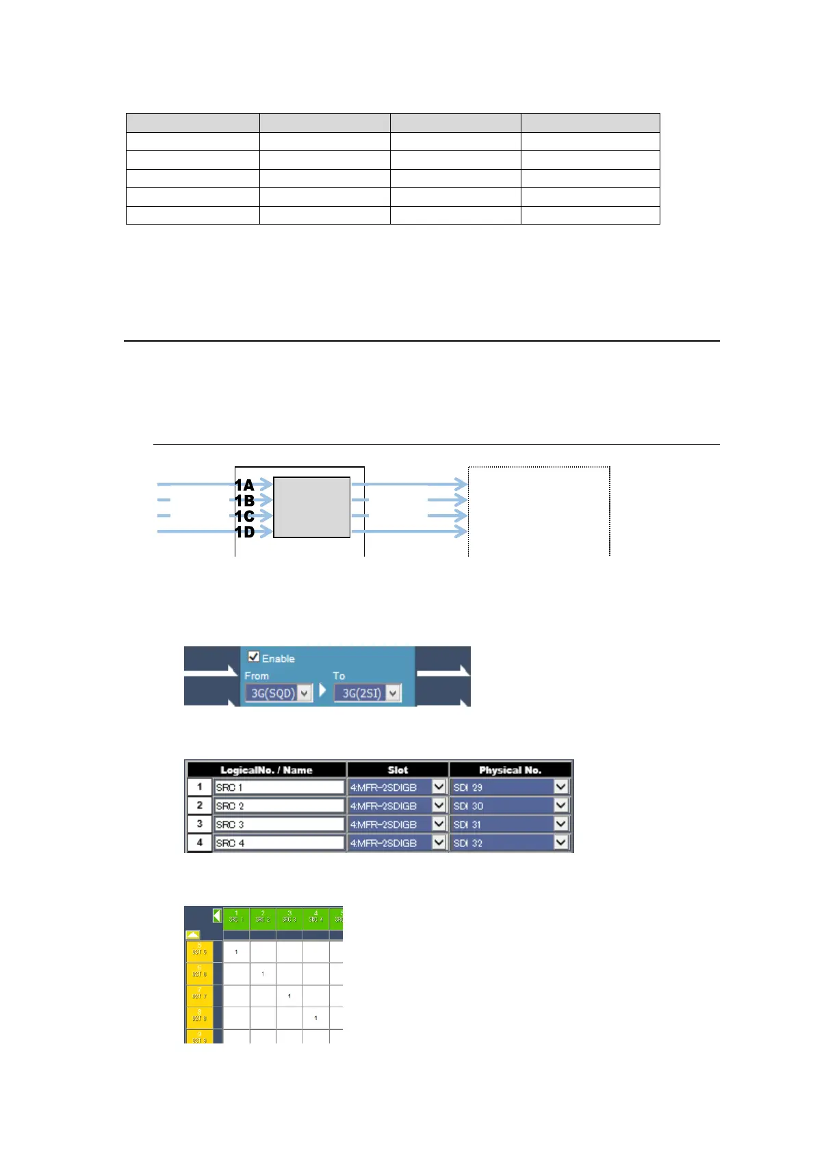
5-3-1. Converting 3G SQD input to 2SI (MFR-2SDIGB)
1. Open the Gearbox Settings page in the WebGUI and select signal formats under
From and To as shown below for a Gearbox in the MFR-2SDIGB card block. (This
example sets Gearbox 1 on the Slot 4 card.)
2. Open the Source Assignment page in the WebGUI and assign the physical
channels (SDI29-32) to logical channels (SRC 1-4).
3. Use a remote control unit or the Crosspoint page in the WebGUI to assign output
channels to SRC1-4.