30
2) Power on the Slave MFR-6000. Set the IP addresses (5 and 6) as shown in the previous
page.
3) Power on the Master MFR-6000.
4) Open the Master MFR-6000 Web-based control and go to the Build Settings page.
Check on Build Enable to enable the Main Unit Link feature.
► See Sec. 11 "Main Unit Link" in the "Web-based Control Operation Manual."
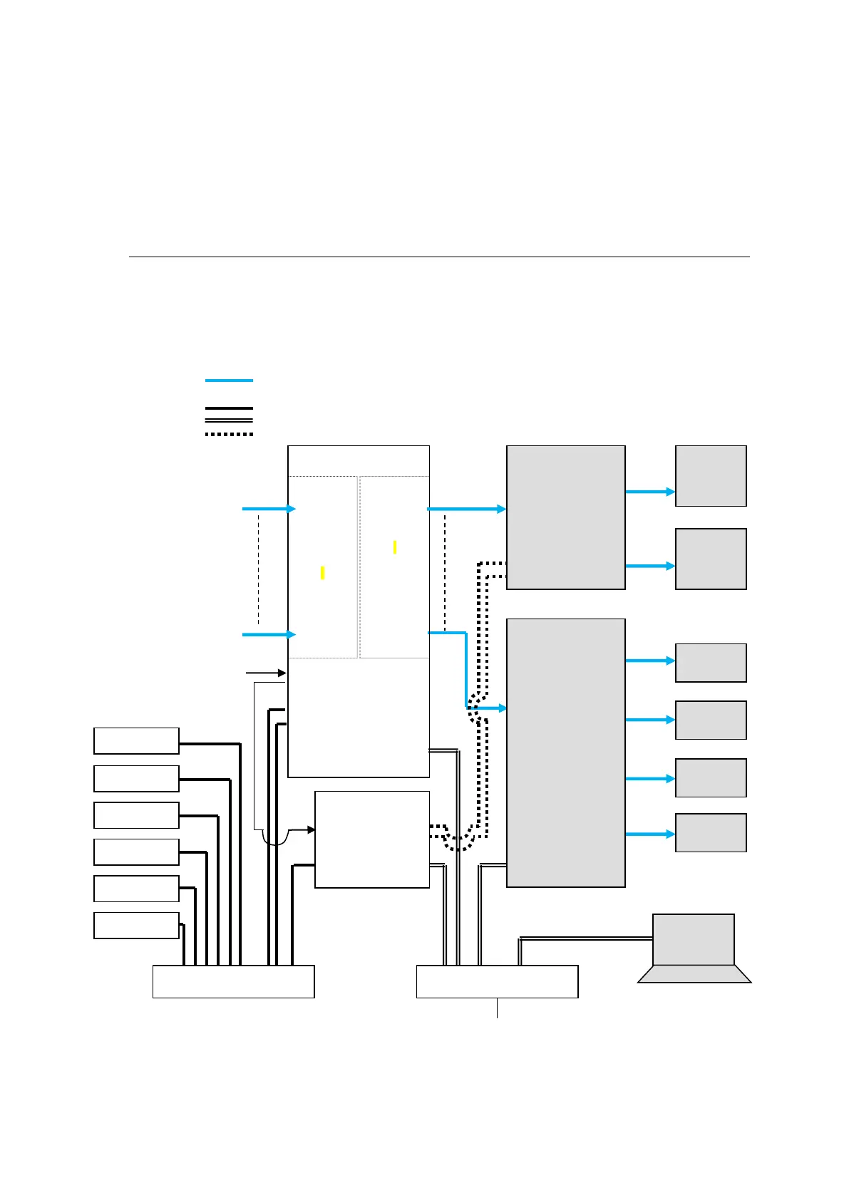
3-3. Configuring the System with MFR-TALM
The block diagram below shows an example signal name and tally link system comprised of a
FOR-A video switcher and multiviewer using an MFR-TALM unit. The MFR-TALM is specifically
designed to perform the task of tally data computation, which is ordinarily undertaken by the MFR
main unit, to accelerate computation. RS-422 ports (1) to (4) are available for video switcher
connection.
VIDEO(SDI)
LAN (MFR-LAN)
LAN (PC LAN)
RS-422
MFR-
9SDI12G
IN1
|
|
|
I
|
|
I
|
IN144
MFR-
9SDO12G
OUT1
|
|
|
I
|
I
|
|
OUT144
MFR Web Control
MV Layout Editor
Video Switcher
(HVS-2000)