EasyManua.ls Logo

FOR-A MFR-6000 - Interfaces

FOR-A MFR-6000
76 pages
Print Icon
To Next Page IconTo Next Page
To Previous Page IconTo Previous Page
Loading...
15
2-2-1. Interfaces
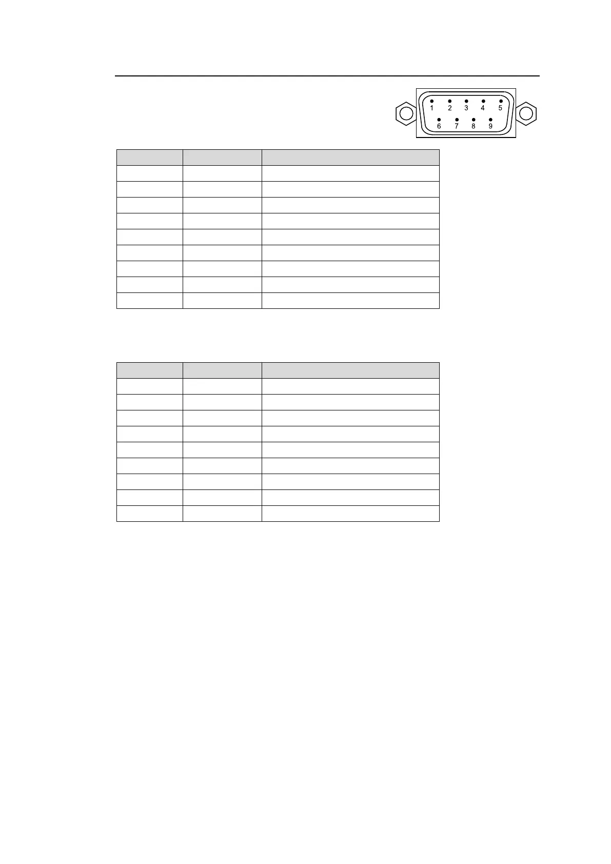
SERIAL Connector (9-pin D-sub, male)
Select RS-232C or RS-422 using the slide switch
at the bottom of the connector.
RS-232C Connector Pin Assignments
Pin No.
Signal Name
Description
1
NC
Not used
2
RxD
Received Data
3
TxD
Transmitted Data
4
DTR
Data Terminal Ready
5
SG
Signal Ground
6
DSR
Data Set Ready
7
RTS
Request to Send
8
CTS
Clear to Send
9
NC
Not used
The maximum cable length is 10 m.
DTR/DSR and RTS/CTS are internally connected respectively.
RS-422 Connector Pin Assignments (Factory default settings)
Pin No.
Signal Name
Description
1
FG
Frame ground
2
T-
Transmit data (-)
3
R+
Receive data (+)
4
SG
Signal Ground
5
NC
Not used
6
SG
Signal Ground
7
T+
Transmit data (+)
8
R-
Receive data (-)
9
FG
Frame Ground
The maximum cable length is 100 m.

Table of Contents

Related product manuals