EasyManua.ls Logo

FOR-A MFR-6000 - Page 16

FOR-A MFR-6000
76 pages
Print Icon
To Next Page IconTo Next Page
To Previous Page IconTo Previous Page
Loading...
16
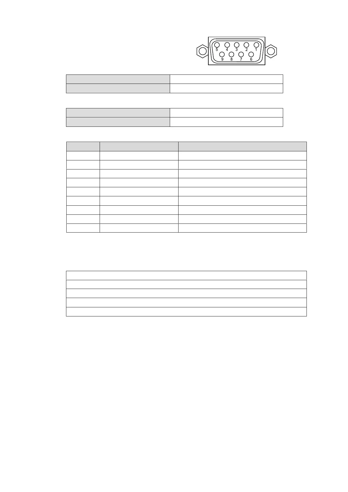
ALARM Connector (9-pin D-sub, female)
Alarm 1 Out:
Normal operation:
Pins 1 and 6 are open.
Malfunction or power-off:
Pins 1 and 6 are closed.
Alarm 2 Out:
Normal operation:
Pins 2 and 7 are open.
Malfunction or power-off:
Pins 2 and 7 are closed.
ALARM Connector Pin Assignments
Pin No.
Signal Name
Description
1
ALARM1 OUT
Alarm 1 output (Default setting: Fan)
2
ALARM2 OUT
Alarm 2 output (Default setting: Power)
3
NC
Not used
4
NC
Not used
5
NC
Not used
6
ALARM 1 COMMON
Alarm 1 output, common
7
ALARM 2 COMMON
Alarm 2 output, common
8
GND
Signal Ground
9
GND
Signal Ground
The following items can be set for ALARM1OUT and ALARM2 OUT. Alarms can be assigned
in Web-based Control.
Available alarm signals
Fan (including power unit cooling fans)
Power
Secondary CPU error
CPU Changeover (issued when activated to change over to secondary CPU operation)
Crosspoint Error

Table of Contents

Related product manuals