34
Setup Settings
1) Connect and assign video signals as shown in the figure on previous page.
2) Device Setup on the MFR-6000:
Connect to the MFR-6000 from the Web-based Control PC and open the [Tally System
Settings - Device Select] page. Select HVS-390HS in the [Switcher] field and click
[Send].
3) Network settings on the MFR-6000:
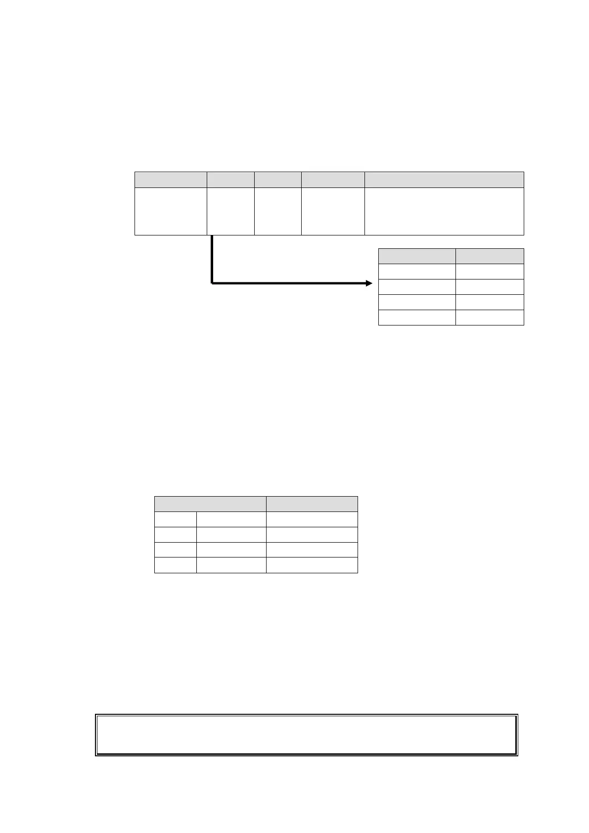
Open the [Router System Settings - PortSettings] page and set the TCP/IP menu as
shown below.
Select a UDP port number.
Do not use the UDP port number
(Default: 23) already used in the
Server (MFR).
4) Assign AUX buses and input channels on the switcher to logical destination and sources
channels on the MFR-6000.
<AUX bus assignments>
a) Open the Destination Assignment page.
b) Select HVS(AUX) under Select Table.
c) Set Level to 1.
d) Assign AUX1 to DST 201.
<Input channel assignments>
a) Open the Source Assignment page.
b) Select HVS(AUX) under Select Table.
c) Set Level to 1.
d) Assign input channels to MFR sources as shown below.
5) Settings on the switcher:
Open the [SETUP - EXT I/F - EDITOR] menu on the HVS-390HS.
Change [TYPE] to [DVS] and [ENABLE] to [ON].
After above setup settings are complete:
If SRC 201 is selected for DST 201, AUX1 outputs IN1 video on the switcher.
If SRC 209 is selected for DST 201, AUX1 outputs STL 3 on the switcher.
If IN4 is selected for AUX1 on the switcher, SRC 204 is selected for DST 201 on the
MFR-6000.
If input channels that are not assigned in the Source Assignment page are selected on the
switcher, they are replaced with the Alternative Source set in the Source Assignment page in
the MFR system.