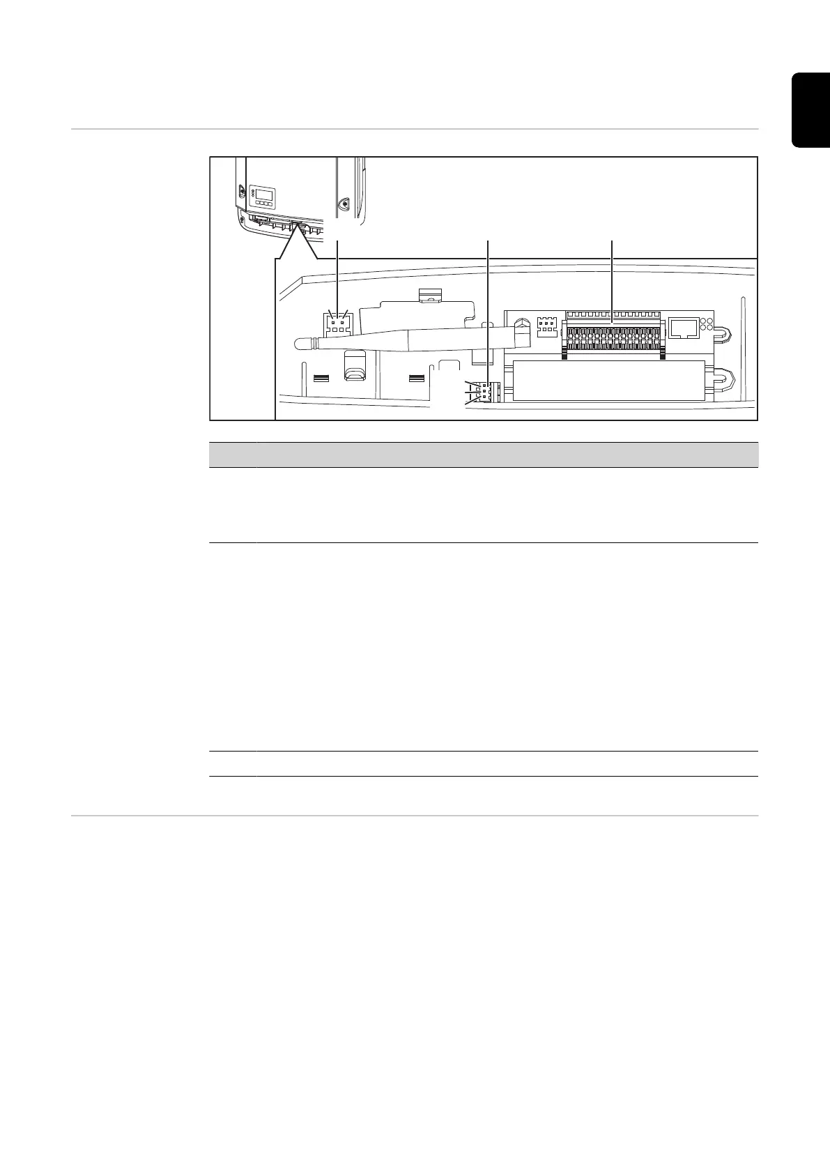
Data communication
Data communica-
tion area
(2)
PIN 1
PIN 2
PIN 1
PIN 2
PIN 3
(3)
(1)
Item Designation
(1) Switchable multifunction current interface
Use the 2-pin mating connector supplied with the inverter to connect to the
multifunction current interface.
(2) Floating switch contact with mating connector
Max. 250 V AC / 4 A AC
Max. 30 V DC / 1 A DC
Max. 1.5 mm² (AWG 16) cable cross-section
Pin 1 = NO contact (normally open)
Pin 2 = C (common)
Pin 3 = NC contact (normally closed)
Use the mating connector supplied with the inverter to connect to the floating
switch contact.
(3) System monitoring with WLAN antenna
General The inverter is fitted with the WLAN-enabled system monitoring and energy management
unit (Fronius Datamanager) as standard.
Various functions are included with the Fronius system monitoring, such as:
37
EN

 Loading...


