No
.
Function
Switch position B
Assigned IP address
System monitoring uses an assigned IP address (factory setting: dynamic
(DHCP))
The IP address can be set on the system monitoring web page.
(2) WLAN LED
- Flashing green: System monitoring is in Service mode
(IP switch on the system monitoring plug-in card is in position A or Service
mode has been activated via the inverter display, the WLAN access point is
open)
- Lights up green: WLAN connection established
- Flashing green/red (alternately): WLAN access point has timed out following
activation (1 hour)
- Lights up red: no WLAN connection
- Flashing red: faulty WLAN connection
(3) Solar.web connection LED
- Lights up green: Fronius Solar.web connection established
- Lights up red: Fronius Solar.web connection is required but has not been
established
- Not lit: no Fronius Solar.web connection is required or the option for sending
data to Fronius Solar.web has been deactivated
(4) Supply LED
- Lights up green: internal communication system is providing an adequate
power supply; system monitoring is ready for use
- Not lit: no power is being supplied by the internal communication system
- Flashing red: update in progress
IMPORTANT! Never interrupt the power supply while an update is in pro-
gress.
- Lights up red: update failed
(5) Connection LED
- Lights up green: good connection within the internal communication system
- Lights up red: connection within the internal communication system has
been interrupted
(6) LAN connection
Ethernet interface, colour-coded blue, for connecting the Ethernet cable
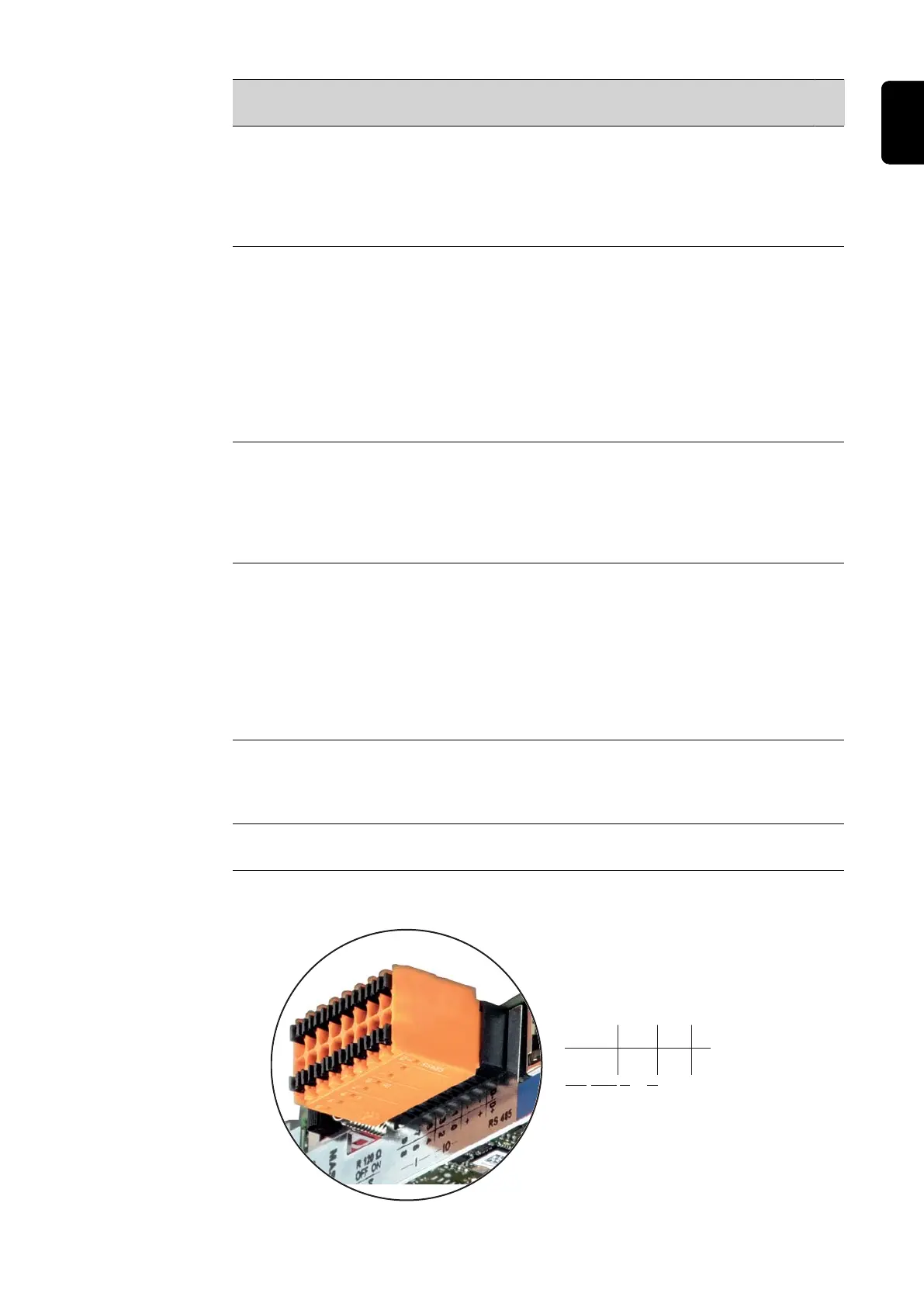
(7) I/Os
Digital inputs and outputs
D-
-
-
1
3
5
7
9
D+
+
+
0
2
4
6
8
I IO RS485
39
EN
 Loading...


