INF-TN1FSC-E 19
6. WIRING
6.1 Diagram
SD
CHARGE DC IN
FEED
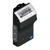
PORTAFLOW
ESC
ON
OFF
Print
ENT
MENU
Printer
(option)
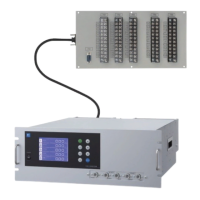
Detector
Detector
Exclusive use signal cable
To connect signal cables for FLD12, FLD22, FLD32, FSDP2, FSDP1, FSDP0
To connect signal cables for FLD41 FLD51
BNC
connector
BNC connector
BNC adaptor
Signal cable
AO analog output 4 to 20mA DC
AICH1 analog input 4 to 20mA DC or 1 to 5 V DC
AICH2 analog input 4 to 20mA DC
Analog input/output cable
AC90 to 264V
Power cord
AC power adaptor
Power connector
Conversion cord
To connect PC
PC
Flow
transmitter
USB cable
SD memory
card
for use AC adaptor
Sensor input
(the downstream side)
Sensor input
(the upstream side)
6.2 Connection of dedicated cables
This cable is used for connecting the detector to the main unit.
(1) Connect dedicated cables to the upstream and downstream sides of the detector.
(2) Connect one cable connected to the upstream side of the detector to the “UP STREAM”
connector of the main unit, and connect the other cable connected to the down stream side
of the detector to the “DOWN STREAM” connector.
DOWN STREAMUP STREAM
Upstream Downstream
Flow direction
Detector

 Loading...