
R
Robin CobbAug 2, 2025
What to do if no picture appears on Furuno Marine Equipment?
- CChristopher RossAug 2, 2025
If no picture is showing on your Furuno Marine Equipment, try pressing the key several times to adjust the screen brilliance.
What to do if no picture appears on Furuno Marine Equipment?
If no picture is showing on your Furuno Marine Equipment, try pressing the key several times to adjust the screen brilliance.
What to do if no data appears on Furuno RD-33?
If no data appears on your Furuno Marine Equipment, check that the connectors of sensors are firmly fastened.
What to do if there is no response when a key is pressed on Furuno Marine Equipment?
If your Furuno Marine Equipment does not respond when a key is pressed, turn the power off and on, then try the key again. If it still doesn't work, the key may be damaged. Contact your dealer for instructions.
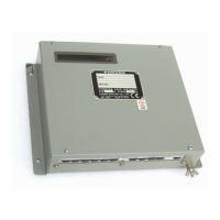
How to fix Furuno RD-33 Marine Equipment that will not turn on?
If your Furuno Marine Equipment will not turn on: • Check that the power cable is firmly fastened. • Check for damaged power cable and connector.
Instructions for proper disposal of the product and used batteries, including environmental considerations.
Warnings and precautions for the operator regarding equipment use, electrical safety, and environmental factors.
Warnings and precautions for installers concerning power supply, grounding, and interference prevention.
Welcome message and overview of the FURUNO RD-33 Remote Display's quality and reliability.
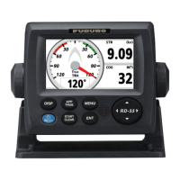
Highlights the main features of the RD-33, including display, data formats, and alarm functions.
Diagrams showing single remote display connections to CAN bus and NMEA 0183 devices.
Illustrates connecting the RD-33 to a NavNet 3D system via the CAN bus line.
Shows how to connect the RD-33 with FI-50 series instruments and a junction box.
Illustrates daisy chain connections and combined NMEA 0183/CAN bus device setups.
Specifies the environmental category for the RD-33 and FI-5002.
Details the function of each control button on the RD-33 unit.
Step-by-step instructions for turning the RD-33 unit on and off.
Guide on how to adjust the LCD screen brightness and key illumination.
Explains how to navigate between different data display screens using the DISP key.
How to select between Analog screen appearances [A] and [B].
Procedure for selecting one of the six programmed screen patterns.
Detailed description and examples of the six programmed screen patterns available.
Guide on how to change display items and properties in factory-preset screens.
Steps to arrange data display and create custom screen layouts.
Details on selecting categories, options, and styles for custom data displays.
Illustrations of various custom data screen layouts.
How to switch between apparent and true wind modes and magnetic/true direction.
Operation of the stopwatch and countdown timer features.
Guide on locking and displaying heading or bearing information.
How to display and configure cross-track error information.
Changing digital data for heading/wind and resetting various values.
Lists alarm types, how they activate, and how to stop audio alarms.
Setting the audio alarm type (Short, Long, Continuous).
Configuration for Arrival/Anchor, XTE, Speed, Water Temperature, Depth, and Trip/Odometer alarms.
Configuration for Roll/Pitch alarms and a description of other alarm types.
Displays all data inputs from connected sensors.
Shows status of connected CAN bus devices and allows nicknaming.
Setting data sources and enabling PGN transmission.
Setting the display format for ship position (latitude/longitude or Loran C).
Configuration for displaying laylines, including angle and history.
Setting measurement units for various data parameters.
Adjusting offsets for depth, wind angle, water temperature, STW, and wind speed.
Configuring data response time and analog meter scale ranges.
Setting display formats for time, date, time difference, and daylight saving time.
Description of remaining system menu items like key beep and language.
Guidelines for regular checks and cleaning to maintain performance.
Procedures for resolving common operational problems.
Performing system and LCD tests to verify correct operation.
Restoring default settings and activating the demonstration mode.
Lists standard and optional supply items for installation.
Guidance on mounting considerations, flush, and desktop installations.
Details on connecting cables, including NMEA 0183 and CAN bus interfaces.
Procedures for initializing and adjusting settings after installation.
Specifies input and output signals in NMEA 0183 and CAN bus formats.
Details display type, picture color, modes, data indication, and language support.
Information on ports, NMEA 0183, and CAN bus PGN data.
Specifies power requirements for CAN bus network and independent operation.
Details ambient temperature, humidity, protection degree, and vibration resistance.
Specifies the unit color code.
| Display Type | LCD |
|---|---|
| NMEA 2000 Compatible | Yes |
| Display Resolution | 320 x 240 pixels |
| Operating Temperature | -15°C to +55°C |
| Interface | NMEA 0183, NMEA 2000 |
| Accuracy | 0.1 knots |
| Depth Range | Up to 200 m |
| Outputs | NMEA 0183 |
| Display | Color |