EasyManua.ls Logo

Furuno RD-33 - Wiring and Connections

Furuno RD-33
96 pages
Print Icon
To Next Page IconTo Next Page
To Previous Page IconTo Previous Page
Loading...
9. INSTALLATION
9-4
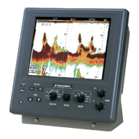
6. Tighten the knobs to fasten the hanger to the remote display.
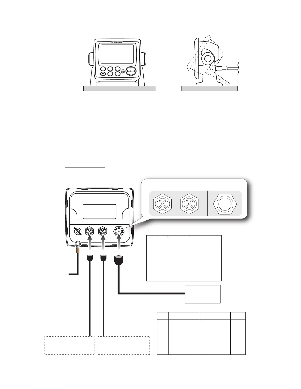
9.3 Wiring
Refer to the following illustration and the interconnection diagram (page S-1) to con-
nect cables.
Note: The remote display power is supplied through CAN bus. When the sensor signal
is input or output only from the NMEA 0183 device without the CAN bus device, con-
nect the 12-24 VDC power from the ship’s switch board to the male connector of the
CAN bus port.
Interconnection
DISP
APP
TRUE
MENU
START
CLEAR
ENT
B
R
I
L
L
FI-50-CHAIN-xxM
(0.3 m, 1 m, 5 m, 10 m, 20 m)
FI-50-CHAIN-xxM
(0.3 m, 1 m, 5 m, 10 m, 20 m)
CAN bus device
(e.g. NavNet 3D)
CAN bus device
(e.g. NavNet 3D)
CAN bus
Pin Signal
Wire color
1
2
3
4
5
FG
NET-S
NET-C
NET-H
NET-L
Drain
Red
Black
White
Blue
+
IV-1.25sq
To ground
terminal on hull
MJ-A6SPF0003-xxxC
(2/5/10/15 m)
NMEA port
Pin Signal Wire color
1
2
3
4
5
6
TD-A
TD-B
RD-A
RD-B
NC
FG
White
Black
Yellow
Green
Shield
Inner dia.
φ
4
N
MEA
p
ort
Pi
l
Wi
l
For CAN bus
(5P Female)
For CAN bus
(5P Female)
For CAN bus
(5P Male)
For CAN bus
(5P Male)
For NMEA 0183
For NMEA 0183
RD-33 (rear)
NMEA 0183
Device
NMEA 0183
Device
M12-05BM+05BF-0xx
(1 m, 2 m, 6 m)
M12-05BM+05BF-0xx
(1 m, 2 m, 6 m)
PWR
The device which
supplies power
or

Related product manuals