9. INSTALLATION
9-5
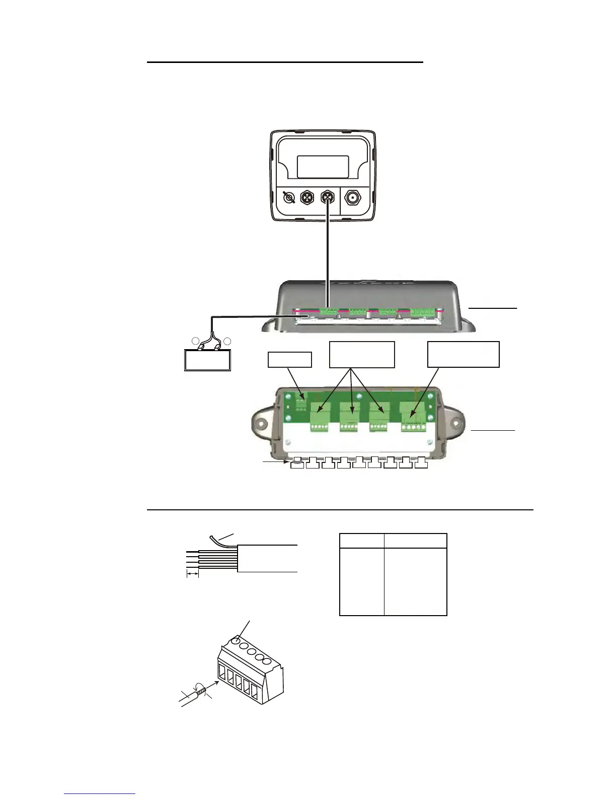
Connection between remote display and junction box
For serviceman: See “Furuno CAN bus Network Design Guide” (TIE-00170-X) for de-
tails about CAN bus network.
Fabrication of cable M12-05BM+05BF-060 and connection to MC connector
12 VDC
White
Black
+
–
Connect to
CN2 - CN5.
12 VDC
CN3 - CN5
DROP
JUNCTION BOX FI-5002 (option)
Fix cable with
supplied cable ties.
FI-5002
Power cable (2 m)
M12-05BM+05BF-0xx
(1 m, 2 m, 6 m)
Side view
Top view
CN2
BACKBONE
MC connector
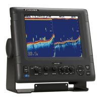
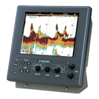
RD-33 (rear)
Power switchboard
Screw
Core
Twist
MC connector
6 mm
Sheath
Cable Fabrication
Drain wire
Wire Conn. Pt.
Drain 1
Red 2
Black 3
White 4
Blue 5
How to insert cores:
1. Twist the cores.
2. Unfasten the screw with
Philips head screwdriver.
3. Set the core to hole.
4. Tighten the screw.
5. Pull the wire to confirm connection.
 Loading...