161
8.2 Electric wiring
8 Electrics/electronics
MITSUBISHI FUSO body/equipment mounting directives for FE Issue date: 20. 10. 2020
! Only print out complete sections from the current version
8.2.7 Fuse
(a) Do not route power wiring from any fuse for
unintended use. The existing fuse on the
chassis side is of the optimum capacity for the
service load, frequency of use, etc. When
installing an additional electrical device
associated with body equipment, do not
connect parts or harnesses which may provide
an error signal to the chassis power line or
ground line.
Be sure to lead out power; for body
equipment-related apparatus and lamps via
designated appropriate connectors. For further
details, see "8.4.3 Mounting location of optional
terminal" É 8.4.3.
Fuses in the cab are provided on the signal
detection and actuation module control unit.
When removing and reinstalling them, do so
securely one by one. For other precautions on
the signal detection and actuation module, see
"8.1.2 Signal detection and actuation
module-related parts" (É 8.1.2).
(b) Mid-point extension of existing wiring or the use
of a larger capacity fuse could cause an
excessive current to flow in the power fuse box,
resulting in a fire.
The power supply voltage may differ depending
upon the fuse. Verify the power supply voltage
by referring to "Power supply voltage" É 8.1.1.
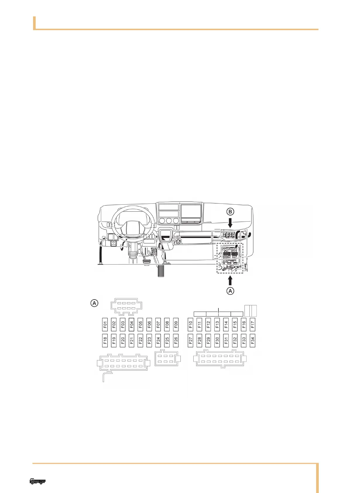
(c) Arrangement of power fuses, relay in the
instrument panel, sensors and ECU
AInside of SAM
1 Spare fuse
12 V Power supply fuse
24 V When the vehicle uses two batteries, a 24 V power supply fuse is installed.
When the vehicle uses one battery, a 12 V power supply fuse is installed.