G1000 / GFC 700 System Maintenance Manual - 300/B300 Series King Air Page 4-27
190-00716-01 Revision 4
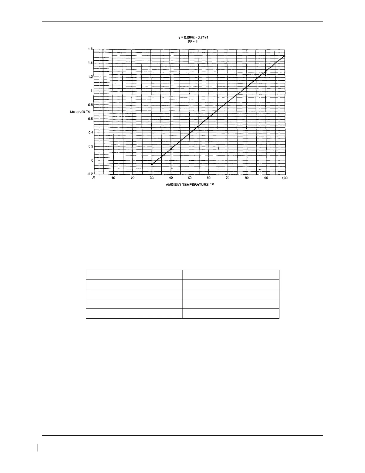
Figure 4-4, Ambient Temperature Conversion Chart
4.11.2 Torque
1. Remove power from aircraft.
2. Disconnect the left engine firewall connector J102.
3. Connect the Signal Generator to pins C (HI) and R (LO) of J102.
4. Apply external power to aircraft and start the G1000 in normal mode.
5. Using the Signal Generator, inject DC signals specified in Table 4-13 and verify the
indications are within the specified tolerances.
Test Point (VDC) Torque Indication (%)
0.000 +/- .02 0 +/- 2
1.035 +/- .02 45 +/- 2
1.725 +/- .02 75 +/- 2
2.300 +/- .02 100 +/- 2
Table 4-13, Torque Indication Test Points
6. On the right hand circuit breaker panel, open the GIA1 (PRI) and GIA1 (SEC) circuit
breakers, and verify the last observed torque indication remains unchanged. Reset the the
GIA1 (PRI) and GIA1 (SEC) circuit breakers.
7. Repeat steps 1 through 5 using right engine firewall connector J103, pins C (HI) and R (LO).
8. Pull the GIA 2 circuit breaker, and verify the last observed torque indication remains
unchanged. Reset the GIA 2 circuit breaker.
9. Remove power from aircraft and reconnect left and right engine firewall connectors.

 Loading...


