Page 6-20 G1000 / GFC 700 System Maintenance Manual - 300/B300 Series King Air
Revision 4 190-00716-01
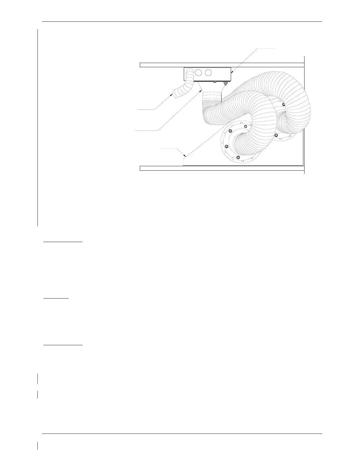
VIEW OF LEFT SIDE NOSE AVIONICS BAY
(NOT ALL ITEMS SHOWN FOR CLARITY)
COOLING FAN HOSE (TYP)
COOLING FAN
NOSE WHEEL WELL HOUSING
FAN INLET DUCT (IF INSTALLED)
P/N 115-00580-02
Figure 6-7, GIA Cooling Fan Inlet Duct Identification
Configuration applicable to MDL 005-00629-00 Rev. 7 or later FAA-approved
revision, or modified per Garmin Service Bulletin 1375
Reinstallation:
1. Reinstallation of the avionics cooling fan is the reverse of the removal. Reference the Electrical
Equipment Install, Nose Bay drawing, listed in Table 1-2, for more details.
2. If further maintenance is not required, proceed to Section 8.
6.30 GDU Cooling Fans
Removal:
1. Remove the display associated with the cooling fan, per Section
6.1.
2. Disconnect the electrical connector of the cooling fan.
3. Use a Phillips screwdriver to remove the attachment screws from the cooling fan.
4. Remove the cooling fan.
Reinstallation:
1. Reinstallation of the Sandia GDU cooling fan is the reverse of the removal. Reference the Main
Instrument Panel Installation drawing, listed in Table 1-2, for more details.
2. If further maintenance is not required, proceed to Section 8.
6.31 GTS 820/850 Traffic Unit
CAUTION:
After any maintenance or modification is made to the GTS 820/850
TAS/TCAS cables such as replacing a connector or entire cable, be
sure to adhere to all of the specifications and limitations such as
minimum and maximum cable attenuation, attenuation balance
between cables, phase matching etc.

 Loading...


