Page 7-42 G1000 / GFC 700 System Maintenance Manual - 300/B300 Series King Air
Revision 4 190-00716-01
7.21 ADF Functional Check
This check verifies that the ADF / G1000 interface operates correctly.
1. Press the PFD softkey on PFD1 and PFD2. Toggle the BRG1 and BRG2 softkey until the ADF
bearing is shown on PFD1 and PFD2.
2. Verify that the ADF window is not invalid (no red ‘X’).
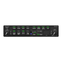
3. Using the ADF control head select a known valid local ADF. Verify that the ADF bearing pointer
moves towards a bearing and stabilizes.
4. Select ADF and SPKR on GMA1 and GMA2. Using the ADF control head, select, ANT mode.
Verify that the audio from the station tuned can be heard on the pilots and copilots headset and
cockpit speaker.
5. Increment the ADF volume control from full low to full high. Verify the volume increases and
decreases appropriately over pilots and copilots headset and cockpit speaker.
If no other service is to be performed, continue to the return-to-service checks in Section 8.
7.22 GRA 5500 Radar Altimeter Functional Check
This check verifies that the G1000/radar altimeter interface is operates correctly.
1. Navigate to the AUX – SYSTEM STATUS page on the MFD.
2. Press the RA TEST softkey and verify that the “RA TEST” annunciation is displayed on both PFDs.
3. Verify 40 feet is displayed in the RA display window on both PFDs.
4. Press the RA TEST softkey again. Verify the RA readout window decreases to 0 feet on PFD1 and
PFD2.
5. Pull the RADIO ALTM circuit breaker. Verify on PFD 1 and PFD 2 that an RA FAIL message is
displayed.
6. Reset the RADIO ALTM circuit breaker.
If no other service is to be performed, continue to the return-to-service checks in Section 8.
7.23 Non-Garmin Radar Altimeter Check
This check verifies that the G1000 / radar altimeter interface is operates correctly.
NOTE
This check only verifies the data output from the G1000 equipment. Any
equipment/wiring added that is not part of the installation data will need separate testing
and verification not covered as part of this document.
1. Navigate to the AUX – SYSTEM STATUS page on the MFD.
2. Press the RA TEST softkey and verify that “RA TEST” annunciation is displayed on both PFDs.
3. Verify 50 feet is displayed in the RA display window on both PFDs.
4. Press the RA TEST softkey again. Verify the RA readout window displays 2500 feet and decreases
to 0 feet on PFD1 and PFD 2.
5. Pull the RADIO ALTM circuit breaker. Verify on PFD 1 and PFD 2 that an RA FAIL message is
displayed.
6. Reset the RADIO ALTM circuit breaker.
If no other service is to be performed, continue to the return-to-service checks in Section 8.
 Loading...


