G1000 / GFC 700 System Maintenance Manual - 300/B300 Series King Air Page 6-11
190-00716-01 Revision 4
6.16.2 GRS 7800 Configuration Module Removal & Replacement
The GRS 7800 configuration module is located on the LRU harness connector strain relief. Refer to the
Master Drawing List, listed in Table 1-2, for specific installation drawings.
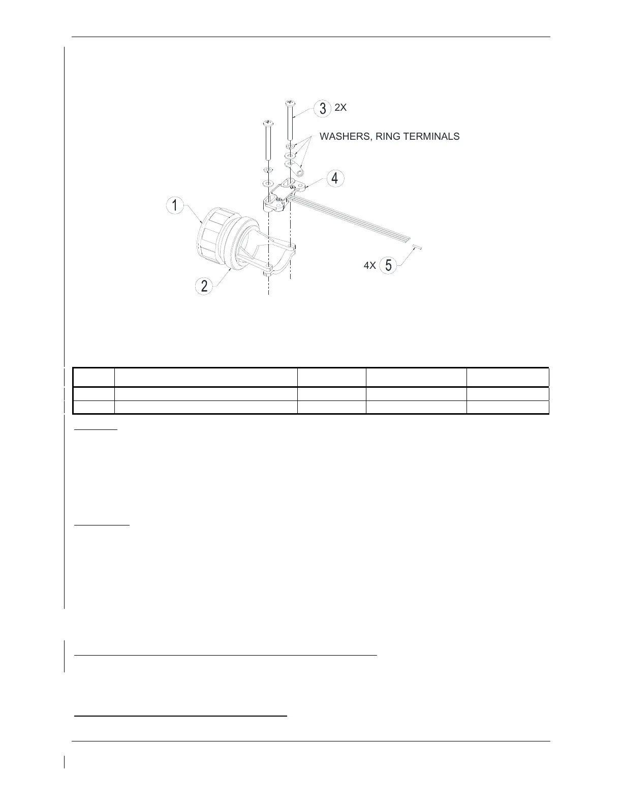
Figure 6-4, GRS 7800 Configuration Module Installation
Table 6-2, GRS 7800 Configuration Module Parts
Item Description Qty Needed Part Number Vendor
4 Configuration Module, Circular Connector 1 011-02582-00 Garmin
5 Socket, Contact 4 M39029/56-348 Best Source
Removal:
1. Disconnect connector (1) from LRU.
2. Remove 2 screws (3), washers, ring terminals and configuration module (4) from strain relief (2).
3. Disconnect the strain relief (2) from the connector (1).
4. Remove the 4 configuration module contact pins from the connector (1).
5. Remove the configuration module (4).
Installation:
1. Inspect connector (1) for damaged pins.
2. Install 4 contact pins (5) on the new configuration module (4) wires.
3. Install the 4 configuration module contact pins (5) into the connector (1).
4. Assembly of the connector and strain relief is the reverse of the disassembly.
5. Continue to Section 6.16.3.
6.16.3 Configuration Module Checkout
If a GRS 77 or GRS 7800 AHRS Configuration Module is replaced:
All three GRS 77 or GRS 7800 and GMU 44 calibration procedures must be performed. Proceed to
Section 7.7.3.
If a GEA 71 Configuration Module is replaced:
Proceed to Section 7.4.1.
2
X
W
A
S
H
E
R
S
,
R
I
N
G
T
E
R
M
I
N
A
L
S
4
X

 Loading...


