GE MEDICAL SYSTEMS
D
IRECTION 2300000, REVISION 1 LOGIQ™ 5 SERVICE MANUAL
Chapter 5 Components and Functions 5 - 11
5-4-5-2 RDS (cont’d)
- Reference Voltage Generator : This mode is for imaging. The parameters specific to scan line
number are sent to OQCARDs and the start triger for receiving signals is generated.
- Access Mode:
This mode is for accessing flash memories and OQCARDs.
5-4-6 FEC
5-4-6-1 Overview
•CHAF:
Three CHAFs have functions of coded excitation decorder and 2nd harmonic filter.
• BIPC and RIF:
Have functions of RF memory controller.
The RIF mainly controls RF memory data bus, RF data flow pass, and RF gain.
The BIPC, which is interface of JUSC bus, mainly controls CHAF and RF memory address bus.
•COMSO:
Has functions of detector, B/M mode edge enhance, Log compression, and dynamic range control.
• PCI IF:
Converts JUSC bus in FEC board. The local bus is connected to each block. It transfers B/M mode
data to PACO FPGA via the COMSO data bus.
• USC IF:
Has functions of generation to JUSC bus, generation of TGC signal and test signal for self-
diagnostics, COMSO control.
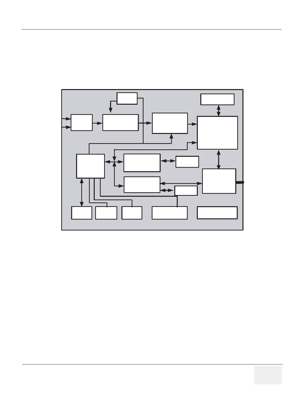
Figure 5-10 FEC Block Diagram
ADDER Harmonic Filter
COMSO
PCI BUS
JUSC
CONTROL
SH-4
for
Scan Control
HV
Control
FEC ASSY
PGC, Test Sig
Gen
COMSO
COMSO
Control
Data
Line Buffer
&
Memory
Controller
Memory
16 MB
PCI I/F for SH-4
Power
Check
Memory
Memory
Clock Gen. Circuit
JUSC
BUS
I960
for
PCI I/F
 Loading...


