GE MEDICAL SYSTEMS
D
IRECTION 2300000, REVISION 2 LOGIQ™5 SERVICE MANUAL
Chapter 8 Replacement Procedures 8-71
8-6-1-4 Removal Procedure (cont’d)
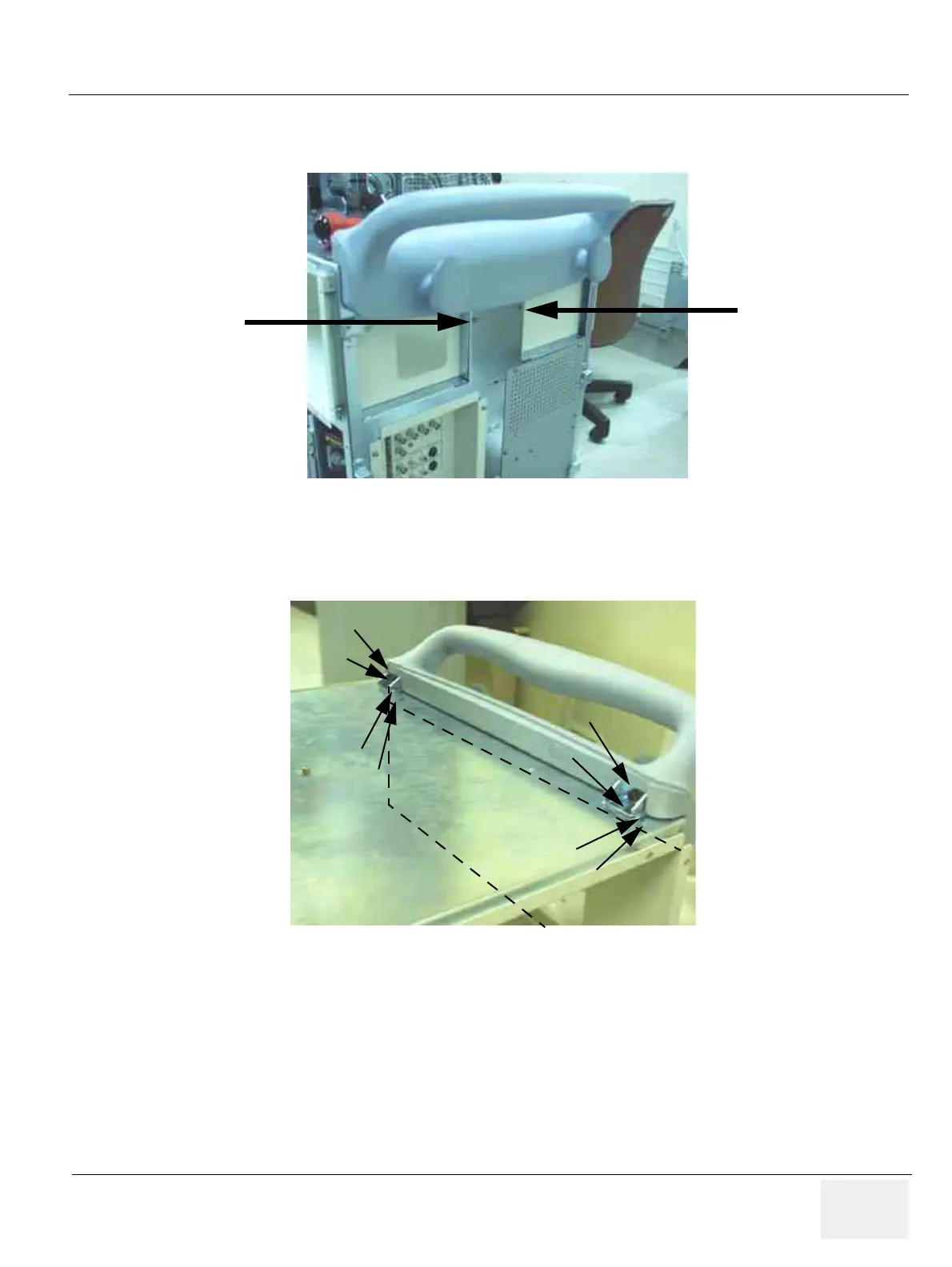
6.) Unscrew two (2) screws (5-6) from the rear side of handle. Refer to Figure 8-71.
7.) Unscrew four (4) screws (7-10) above top plate surface on the Rear Handle.
8.) Unscrew four (4) screws (11-14) below top plate surface on the Rear Handle. Refer to Figure 8-72.
9.) Remove the Rear Handle.
Figure 8-71 Unscrew two screws
Figure 8-72 Removing the Rear Handle
(5)
(6)
(7)
(8)
(11)
(12)
(9)
(10)
(13)
(14)
Top Plate surface
Rear Handle
 Loading...


