GE MEDICAL SYSTEMS
D
IRECTION 2300000, REVISION 1 LOGIQ™ 5 SERVICE MANUAL
Chapter 5 Components and Functions 5 - 19
5-7-2 Peripherals and Cable connection
A VCR, a Black & White Video Printer and a Color Printer may be installed onboard the scanner. These
devices are connected to the External I/O (Rear Panel) or Front Panel in the case of B/W Printer.
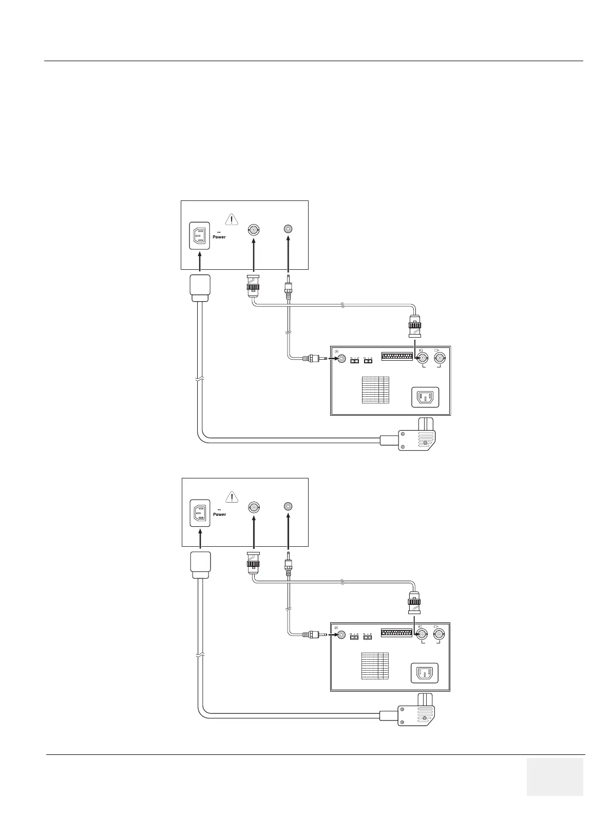
5-7-2-1 B/W Printer Cable Connection (Analog and Digital)
Connect the Power cable, mini plug cable, and the BNC-BNC cable between the B/W Video Printer and
the console as shown in Figure 5-16 on page 5-19 .
Figure 5-16 Cable Connection - USB Cable and Analog Connection Method
100~120V 500VA Max
Composite B/W
B/W Printer
REMOTE GAMMA
DIP SW FUNCTION TABLE
POWER CABLE
Rear Panel of B/W Printer
BNC-BNC CABLE
MINI PLUG CABLE
DIP SW
OFF
PAPER
TYPE
ON
IN
III
III
IIIIV
VEDEO
~AC IN
OUT
100~120V 500VA Max
Composite B/W
B/W Printer
REMOTE GAMMA
DIP SW FUNCTION TABLE
POWER CABLE
Rear Panel of B/W Printer
BNC-BNC CABLE
MINI PLUG CABLE
DIP SW
OFF
PAPER
TYPE
ON
IN
III
III
IIIIV
VEDEO
~AC IN
OUT
Analog Cable Connection
Digital (USB) Cable Connection