GE MEDICAL SYSTEMS
DIRECTION 2300000, REVISION 2 LOGIQ™5 SERVICE MANUAL
8-20 Section 8-4 - Keyboard Block
8-4-3 Probe Holder
Purpose: This is a description on how to remove and replace the Probe Holder.
8-4-3-1 Tools
• Not Required
8-4-3-2 Needed Manpower
• 1persons, 1 minute + travel
8-4-3-3 Preparations
none
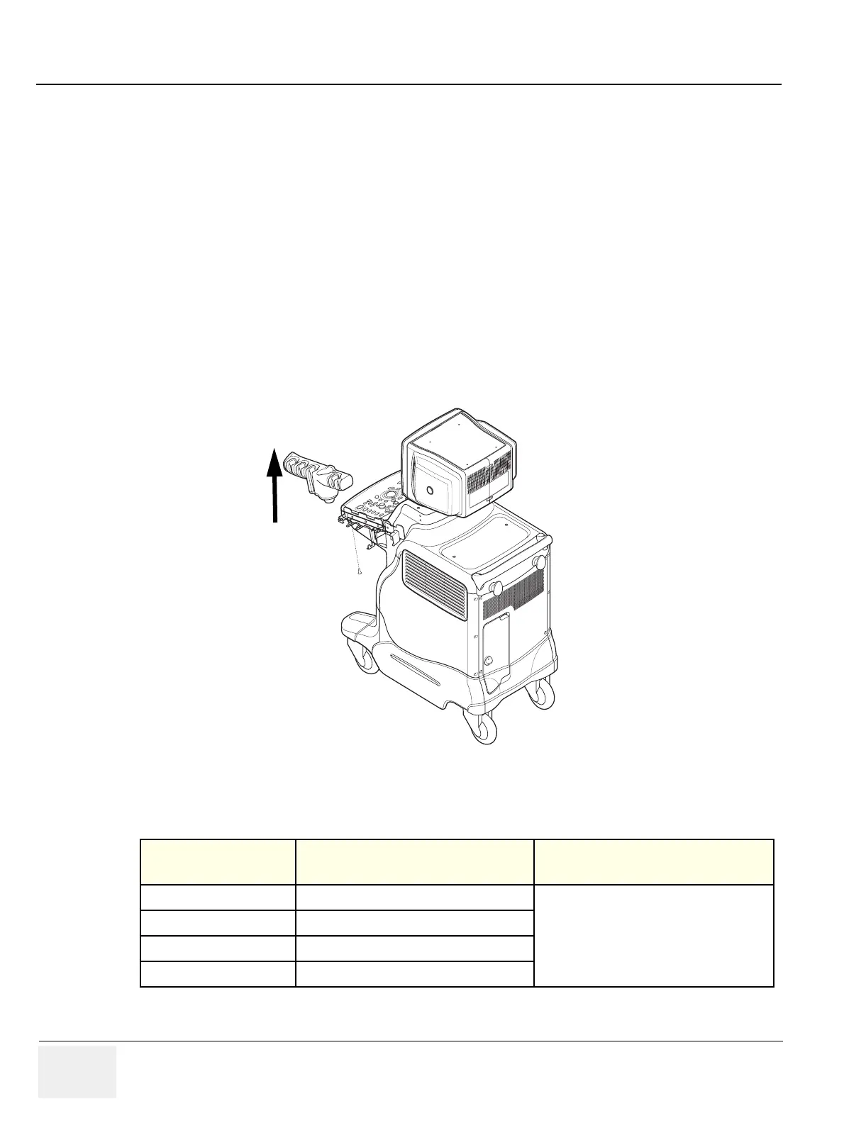
8-4-3-4 Removal Procedure
1.) Remove PG Rivet from the Probe Holder Assy.
2.) Lift the Probe Holder from the Bracket. Refer to Figure 8-25.
3.) Perform the following functional tests. If all are successful, include the debrief script provided below.
8-4-3-5 Mounting procedure
Install the new parts in the reverse order of removal.
Figure 8-25 PROBE HOLDER DISASSEMBLY
Table 8-10 Functional Tests
Service Manual
Section
Functional Test / Diagnostic Test Debrief Script
Section 4-3-1
Power On/Boot Up
“Service Manual, Direction
2300000, Rev 1+, Section 8-4-3. Equipment
passed all required tests and is ready for use. “
Section 4-3-2
Power Off / Shutdown
Section 4-8-2-3
Probe holder
Section 10-5-5
Physical Inspection
P.G. Rivet
Lift
 Loading...


