GE MEDICAL SYSTEMS
D
IRECTION 2300000, REVISION 2 LOGIQ™5 SERVICE MANUAL
Chapter 8 Replacement Procedures 8-79
8-6-3 Gas Spring Assy
Purpose: This is a description on how to remove and replace the Up/Down Assy.
8-6-3-1 Tools
• Common pillips screwdrivers
• Allen/Unbraco wrench
• E-ring gripper
8-6-3-2 Needed Manpower
• 1 person, 45 minutes + travel
8-6-3-3 Preparations
• Shut Down the System and switch off the Main Breaker at the rear as described in section 4-3-2 on
page 3.
• Removal of following parts should be proceeded before start.
• Remove CRT Assy, KeyBoard Assy, Probe Holder,Left Cover, Right Cover, Front Base Cover,
Front Cover, OP Side L Cover, OP Side R Cover, OP Rear Cover, EMI Cover L, EMI Cover R,
BackPlane, and BEP (Back End Processor) ASSY.
8-6-3-4 Removal Procedure
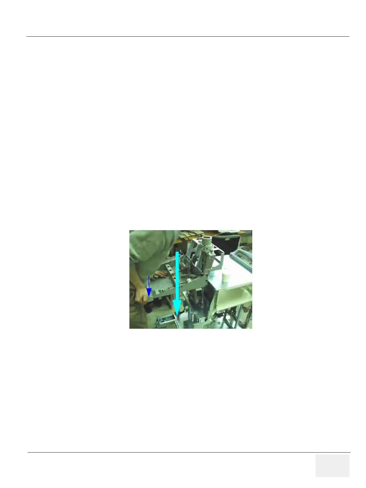
1.) Lower the OP Frame down to its lowest position. Refer to Figure 8-80.
2.) Unscrew three (3) screws (1-3) to remove the OP push button.
Figure 8-80 Lowering the OP Frame
Release Button
PRESS
 Loading...


