GE MEDICAL SYSTEMS
DIRECTION 2300000, REVISION 2 LOGIQ™5 SERVICE MANUAL
8-86 Section 8-6 - Body Block
8-6-6 Bumper Set
Purpose: This is a description on how to remove and replace the Bumper Set.
8-6-6-1 Tools
• Common pillips screwdrivers
8-6-6-2 Needed Manpower
• 1persons, 20 minutes + travel
8-6-6-3 Preparations
• Shut Down the System and switch off the Main Breaker at the rear as described in section 4-3-2 on
page 3.
8-6-6-4 Removal Procedure
1.) Remove the Monitor Assy. Refer to section 8-3-1 on page 2.
2.) Remove the Left Cover. Refer to section 8-5-1 on page 39.
3.) Remove the Right Cover. Refer to section 8-5-2 on page 41.
4.) Remove the Front Base Cover. Refer to section 8-5-6 on page 49.
5.) Unscrew two screws (1-2).
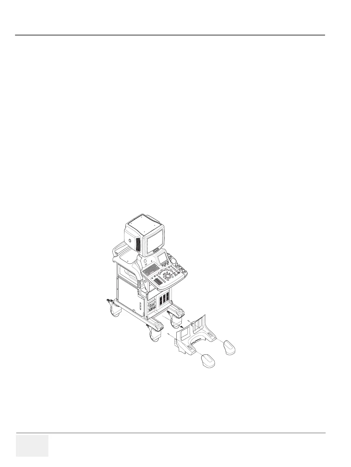
6.) Remove the Bumper Set. Refer to Figure 8-86.
Figure 8-86 Removing the Bumper Set
1
2