GE MEDICAL SYSTEMS
D
IRECTION 2300000, REVISION 2 LOGIQ™5 SERVICE MANUAL
Chapter 8 Replacement Procedures 8-99
8-7-5 DC Fan Assy
Purpose: This is a description on how to remove and replace the DC Fan.
8-7-5-1 Tools
• Common pillips screwdrivers
8-7-5-2 Needed Manpower
• 1 persons, 20 minutes + travel
8-7-5-3 Preparations
• Shut Down the System and switch off the Main Breaker at the rear as described in section 4-3-2 on
page 3.
8-7-5-4 Removal Procedure
1.) Remove the Right Cover. Refer to section 8-5-2 on page 41.
2.) Remove the EMI Cover R. Refer to section 8-5-14 on page 64.
3.) Unscrew the five screws from the Nest EMI Cover.
4.) Remove the Nest EMI Cover.
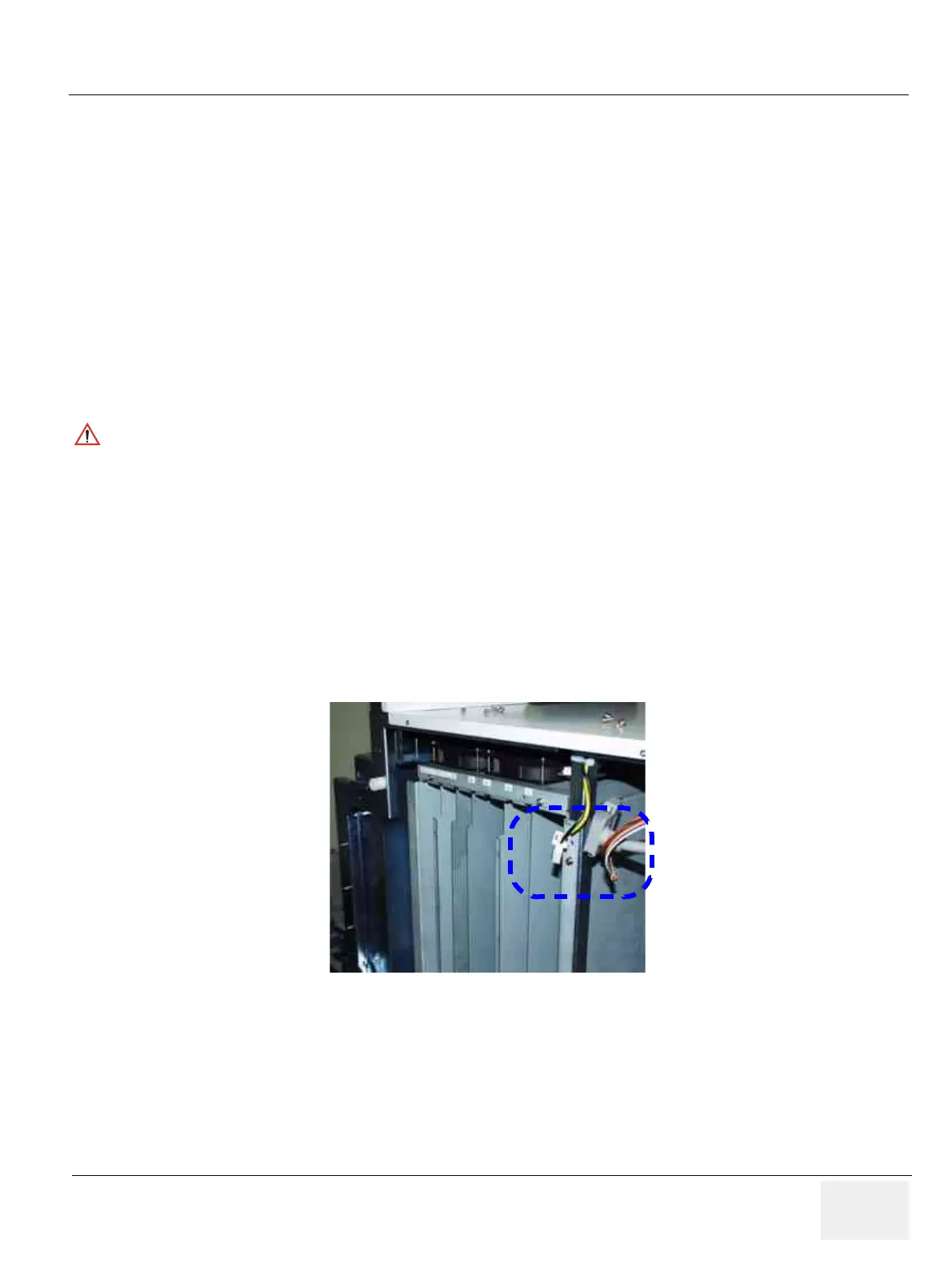
5.) Disconnect one (1) connector (1).
6.) Unscrew two (2) screws (2-3) to remove DC Fan Assy.
CAUTION
An electronic discharge may damage a component. Turn OFF power and wear the wrist strap
before you remove circuit boards. Do not unplug the power cord to keep ground continuity.
Do not bend or flex the boards when mounting/dismounting each boards. Surface mount IC
boards are very susceptible to damage from flex/torque.
Figure 8-97 Removing the DC Fan Assy
 Loading...


