GE MEDICAL SYSTEMS
DIRECTION 2300000, REVISION 1 LOGIQ™ 5 SERVICE MANUAL
6 - 2 Section 6-3 - Power Supply Adjustment
6-3-1 LV Unit Disassembly
This system contains three power supply modules; HV unit, LV unit, and ATX PS. However, the LV unit
only can be adjusted.
6-3-1-1 Tools
• Common pillips screwdrivers
• Allen/Unbraco wrench
• Long-nose gripper
6-3-1-2 Needed Manpower
• 1 person, 15 minutes + travel
6-3-1-3 Preparations
• Shut Down the System and switch off the Main Breaker at the rear as described in section 4-2-2 on
page 5.
• Remove the AC Power assy from the System
6-3-1-4 Removal Procedure
1.) Unscrew four (4) screws (1-4) to remove Left side cover of AC Power assy.
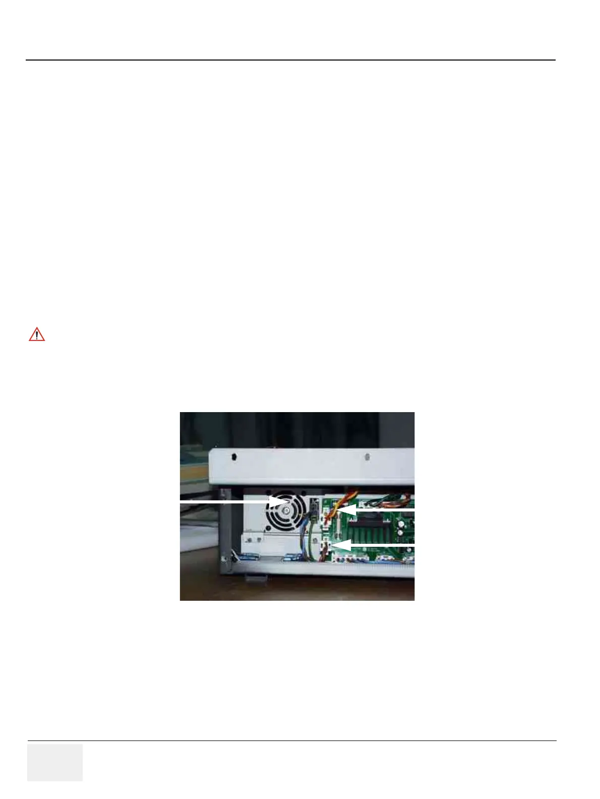
2.) Disconnect three (3) connectors from the rear side of the LV Unit. Refer to .
3.) Unscrew four (4) screws (8-11) to remove Right side cover of AC Power assy.
CAUTION
Do not wear the ESD wrist strap when you remove a part of power supply unit. Turn OFF power
and unplug the power cord before removing a part of power supply unit. However be sure to turn
off power and wear the strap before you remove a circuit boards.
Figure 6-1 Disconnect 3 connectors
Connector
Connector
Connector
 Loading...


