GE MEDICAL SYSTEMS
D
IRECTION 2300000, REVISION 2 LOGIQ™5 SERVICE MANUAL
Chapter 8 Replacement Procedures 8-33
8-4-10 OP Panel HUB board Assy
Purpose: This is a description on how to remove and replace HUB board Assy.
8-4-10-1 Tools
• Common pillips screwdrivers
8-4-10-2 Needed Manpower
• 1persons, 5 minutes + travel
8-4-10-3 Preparations
• Shut Down the System and switch off the Main Breaker at the rear as described in section 4-3-2 on
page 3.
• Keyboard Assy should be removed before proceed. For more information, refer to KeyBoard Assy
on section 8-4-1 on page 15.
8-4-10-4 Removal Procedure
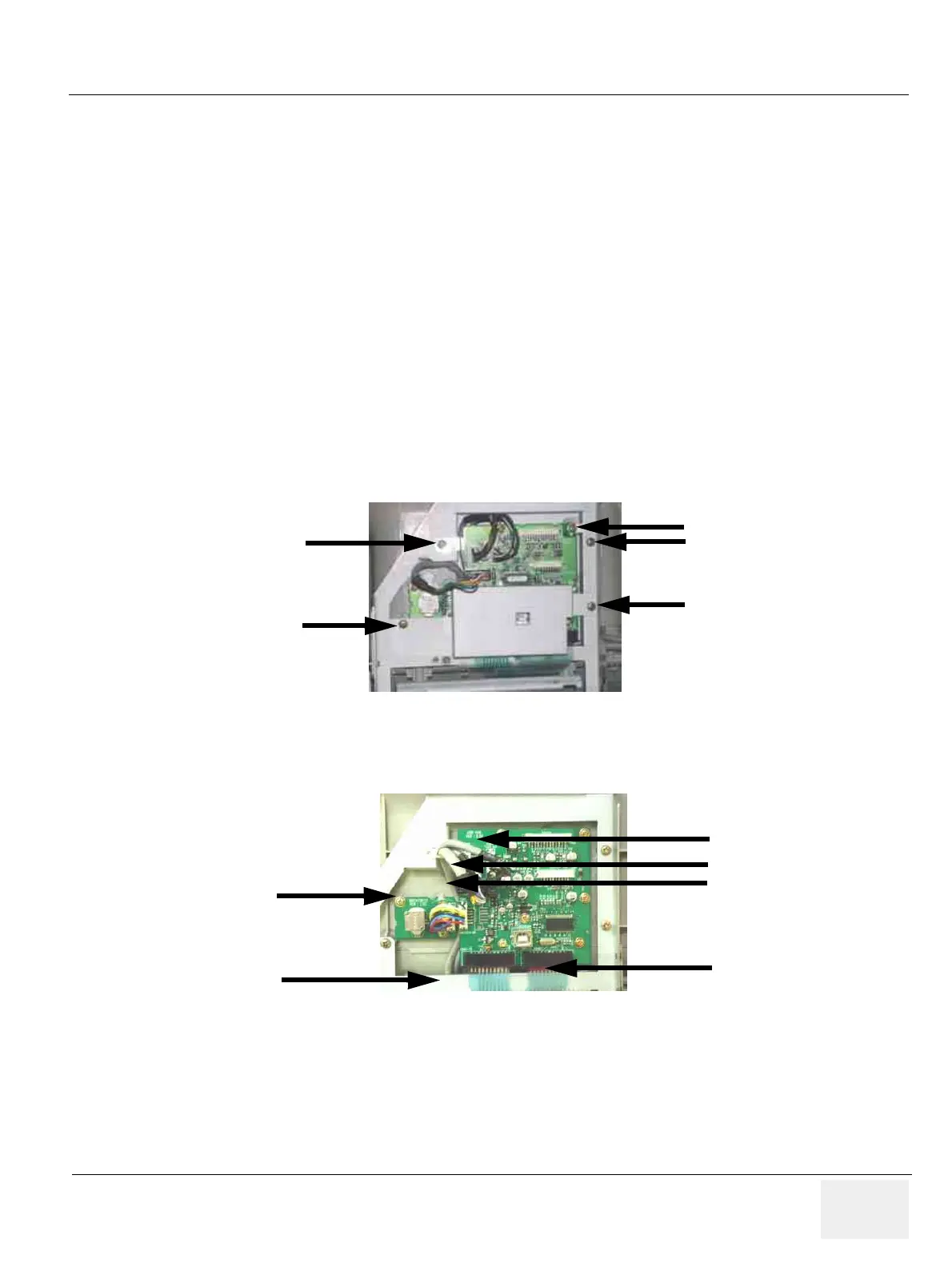
1.) Unscrew five (5) screws and remove the EMC guard from the HUB Board. Refer to Figure 8-39.
2.) Disconnect six (6) connectors (1-6) from the HUB Board Assy. Refer to Figure 8-40.
Figure 8-39 Removing EMC guard
Figure 8-40 Disconnect 6 connectors
1
2
3
4
5
1
2
3
4
5
6