GE MEDICAL SYSTEMS
D
IRECTION 2300000, REVISION 2 LOGIQ™5 SERVICE MANUAL
Chapter 8 Replacement Procedures 8-153
Section 8-9
Power Block
8-9-1 AC Power Assy
Purpose: This is a description on how to remove and replace the AC Power Assy.
8-9-1-1 Tools
• Common pillips screwdrivers
8-9-1-2 Needed Manpower
• 2 persons, 15 minutes + travel
8-9-1-3 Preparations
• Shut Down the System and switch off the Main Breaker at the rear as described in section 4-3-2 on
page 3.
8-9-1-4 Removal Procedure
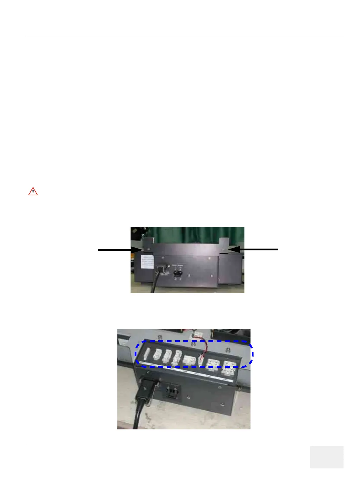
1.) Unscrew two(2) screws (1-2) to remove rear connector bracket. Refer to Figure 8-182.
2.) Disconnect eight (8) connectors (3-10). Refer to Figure 8-183.
CAUTION
Do not wear the ESD wrist strap when you remove a part of power supply unit. Turn OFF power
and unplug the power cord before removing a part of power supply unit. However be sure to turn
off power and wear the strap before you remove a circuit boards.
Figure 8-182 Removing the Rear Connector Bracket
Figure 8-183 Disconnecting 8 connecotors
(1)
(2)
(3) (4) (5) (6)
(7) (8) (9) (10)
 Loading...


