GE MEDICAL SYSTEMS
D
IRECTION 2300000, REVISION 2 LOGIQ™5 SERVICE MANUAL
Chapter 8 Replacement Procedures 8-5
8-3-2 Monitor Cable Assy
Purpose: This is a description on how to remove and replace the Monitor Assy.
8-3-2-1 Tools
• Common pillips screwdrivers
•Cutter
8-3-2-2 Needed Manpower
• 1person, 5 minutes + travel
8-3-2-3 Preparations
• Shut Down the System and switch off the Main Breaker at the rear as described in section 4-3-2 on
page 3.
• Maneuver Control Console to a suitable position for removing the monitor.
8-3-2-4 Removal procedure
1.) Remove the OP Rear Cover. Refer to section 8-5-10 on page 56.
2.) Remove the Monitor Covers. For more information, refer to 8-3-3 "Monitor Cover Set" on page 8-7.
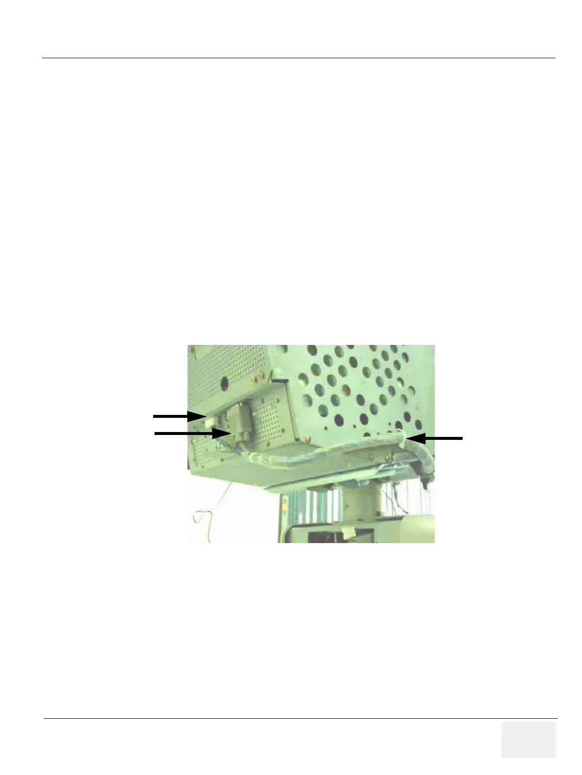
3.) Disconnect two connectors (1-2) and cut the tie wrap in the location (3). Refer to Figure 8-7.
Figure 8-7 Disconnect Connectors and Cut the tiewrap
Tie wrap
Connector 1
Connector 2