GE MEDICAL SYSTEMS
DIRECTION 2300000, REVISION 2 LOGIQ™5 SERVICE MANUAL
8-6 Section 8-3 - Monitor
8-3-2-4 Removal procedure (cont’d)
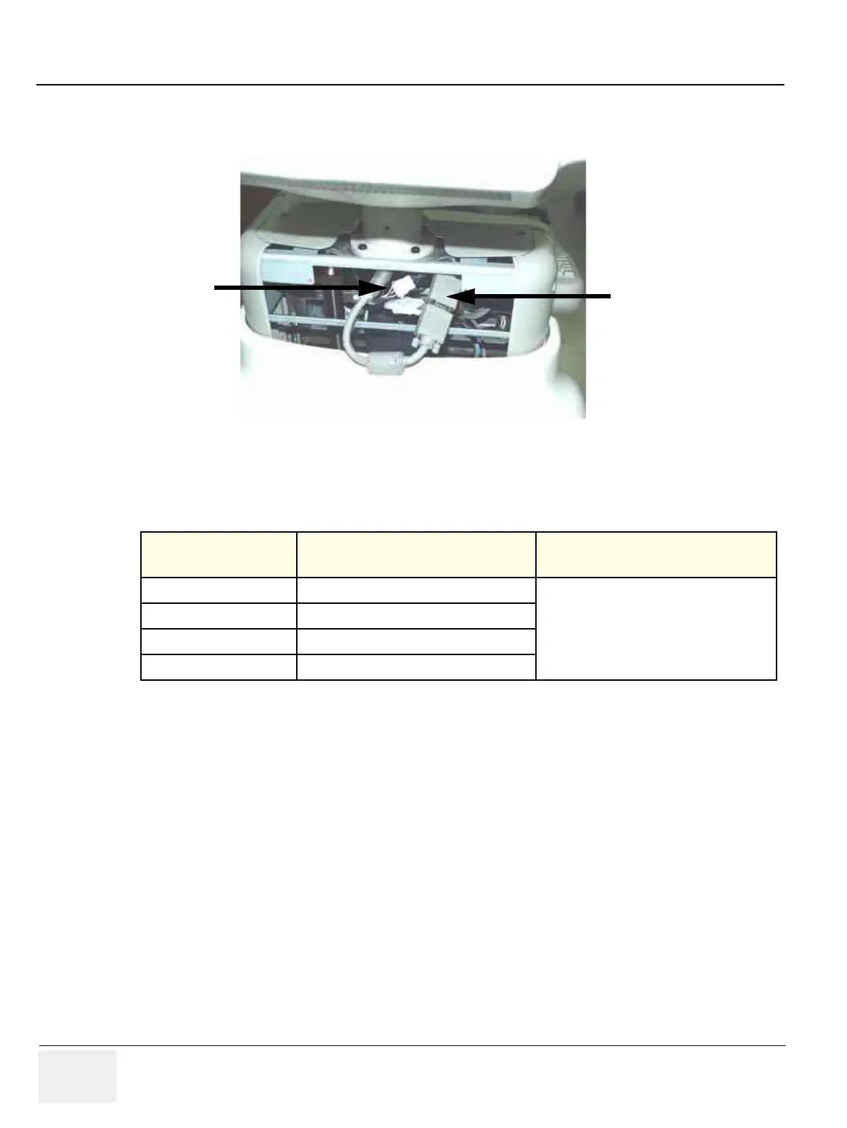
4.) Disconnect two connectors on the other end (4-5). Refer to Figure 8-8.
5.) Pull the Cable Assy out from the OP Rear Cover.
6.) Perform the following functional tests. If all are successful, include the debrief script provided below.
8-3-2-5 Mounting procedure
Install the new parts in the reverse order of removal.
Figure 8-8 Disconnect two(2) Connectors (5-6)
Table 8-3 Functional Tests
Service Manual
Section Functional Test / Diagnostic Test Debrief Script
Section 4-3-1
Power On/Boot Up
“Service Manual, Direction
2300000, Rev 1+, Section 8-3-2. Equipment
passed all required tests and is ready for use. “
Section 4-3-2
Power Off / Shutdown
Section 4-6-3
Monitor Cable Assy function check procedure
Section 10-5-2
Functional Checks (See Also Chapter 4)
5
4
 Loading...


