GE MEDICAL SYSTEMS
DIRECTION 2300000, REVISION 2 LOGIQ™5 SERVICE MANUAL
8-80 Section 8-6 - Body Block
8-6-3-4 Removal Procedure (cont’d)
3.) Unscrew two (3) screws (4-6) to remove the OP button bracket. Refer to Figure 8-81.
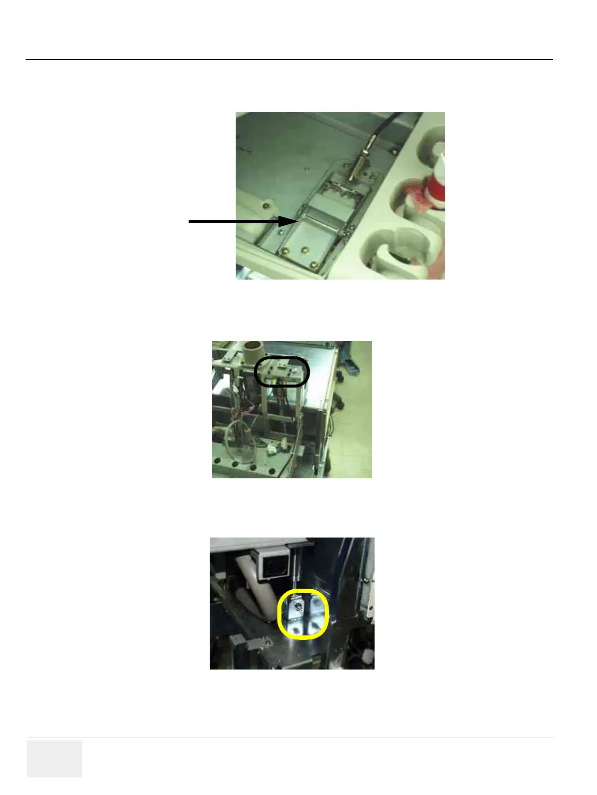
4.) Unscrew four (4) hexagon screws (7-10). Refer to Figure 8-82.
5.) Using E-ring gripper, remove E-ring. Refer to Figure 8-83.
6.) Pull the Gas-spring out upward.
Figure 8-81 Unscrew 6 screws to remove BRKT
Figure 8-82 Unscrew 4 hexagon screws
Figure 8-83 Remove E-Ring
(1)
(2)
(3)
(4)
(5)
(6)
OP Button Bracket
E-RING
 Loading...


