GE MEDICAL SYSTEMS
D
IRECTION 2300000, REVISION 1 LOGIQ™ 5 SERVICE MANUAL
Chapter 5 Components and Functions 5 - 13
5-4-7 HV Power(Tx Power)
5-4-7-1 Overview
AC110V is supplied to the HV unit via AC Box > Transformer > SSR. This is applied to the PFC, inside
the HV unit. The PFC convert AC100V to DC400V, and DC voltage is applied to DC/DC, then to HVH,
HVL, and SHV using dropper. They convert DC voltage to proper voltage to be outputted.
5-4-7-2 Specifications
DC Output Capacity:
• HVH : +/- 0V to +/- 60V variable, Max. 110W, Max. 2A
• HVL : +/-0V to +/- 30V variable, Max, 70W, 1A
• +SHV: +80V +/- 5%, 80mA
• -SHV: -80V +/- 5%, 80mA
5-4-7-3 Output Signal to FEC
The following signals are sent to FEC via BACKPLANE board.
• OV(Over Voltage), OC(Over Current) of each power source : HV tests in itself. The result transmits
the FEC via BACKPLANE ASSY.
5-4-7-4 Input Signal from FEC
The following signals are sent to HV unit via FEC > BACKPLANE board.
• +5V, +/- 15V, HV STOP: These signals are sent to PFC to control DC voltage output of HVH, HVL,
and -SHV. Normally HVSTOP is ON
- HVH Ref, HVL Ref: These are the digital signals (8 bits) sent to the DAC of HVH or HVL from
FEC. Consequently, The DC Voltage (0 - 60V) is outputted from HV unit.
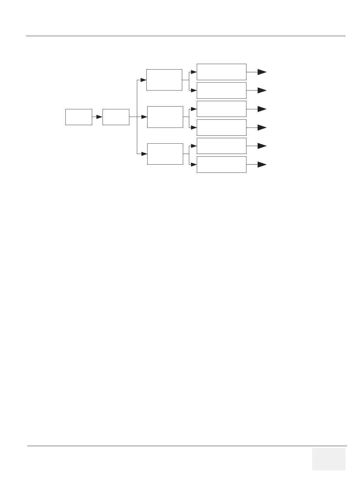
Figure 5-11 HV Unit Block Diagram
AC_IN PFC
PWM1
(HVH)
PWM2
(HVL)
PWM3
(SHV)
DROPPER1
DROPPER1
DROPPER2
DROPPER2
DROPPER3
DROPPER3
+HVH
(0 ~ 60V
-HVH
(0 ~ -60
+HVL
(0 ~ 30V
-HVL
(0 ~ -30
+SHV
(0 ~ 80V
-SHV
(0 ~ -80