GE MEDICAL SYSTEMS
DIRECTION 2300000, REVISION 2 LOGIQ™5 SERVICE MANUAL
8-36 Section 8-4 - Keyboard Block
8-4-11-4 Removal Procedure (cont’d)
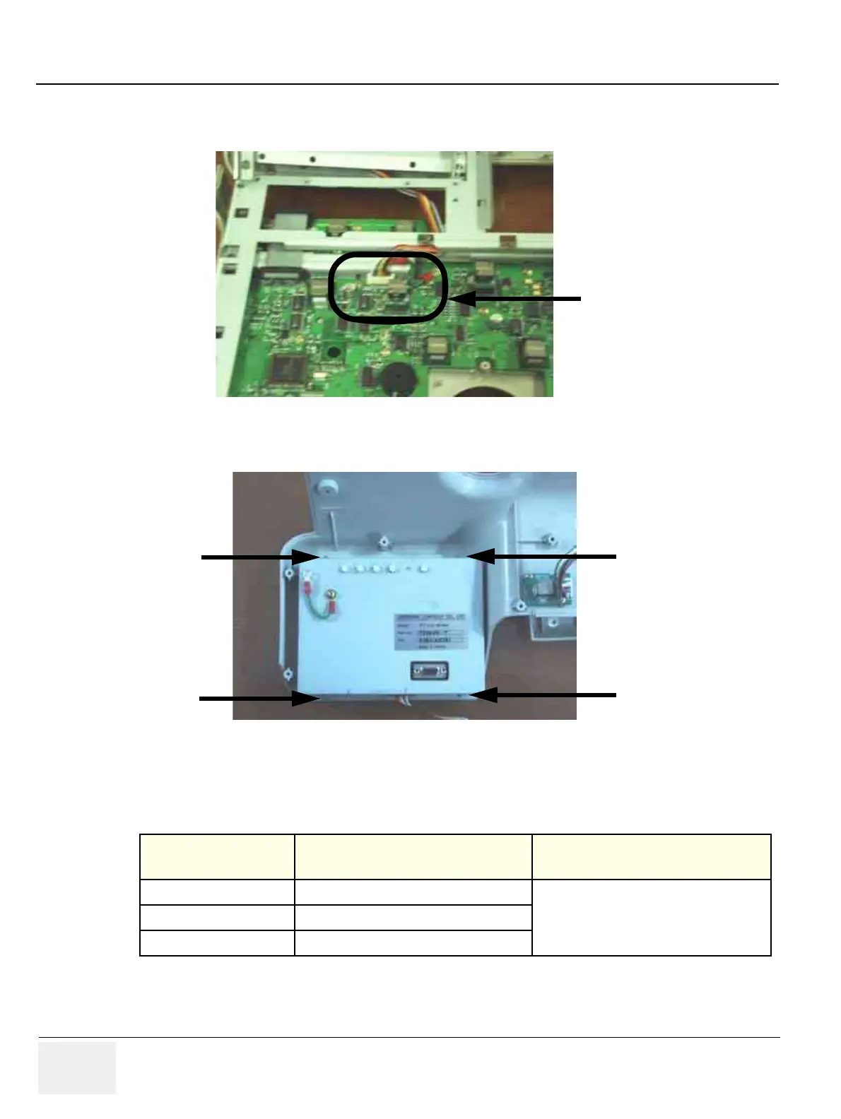
2.) Disconnect one connector (11) from the main circuit board in the keyboard. Refer to Figure 8-43.
3.) Unscrew four (4) screws (12-15) from the LCD unit. Refer to Figure 8-44.
4.) Remove the LCD Assy from the Keyboard.
5.) Perform the following functional tests. If all are successful, include the debrief script provided below.
8-4-11-5 Mounting Procedure
Install the new parts in the reverse order of removal.
Figure 8-43 Disconnect one connector
Figure 8-44 Unscrew 4 screws from the LCD unit
Table 8-18 Functional Tests
Service Manual
Section Functional Test / Diagnostic Test Debrief Script
Section 4-3-1
Power On/Boot Up
“Service Manual, Direction
2300000, Rev 1+, Section 8-4-11. Equipment
passed all required tests and is ready for use. “
Section 4-3-2
Power Off / Shutdown
Section 4-7-8
OP Panel LCD Assy Validation
(11)
(13)
(14)
(12)
(15)
LCD Unit
 Loading...


