GE MEDICAL SYSTEMS
DIRECTION 2300000, REVISION 2 LOGIQ™5 SERVICE MANUAL
8-74 Section 8-6 - Body Block
8-6-2-4 Removal Procedure (cont’d)
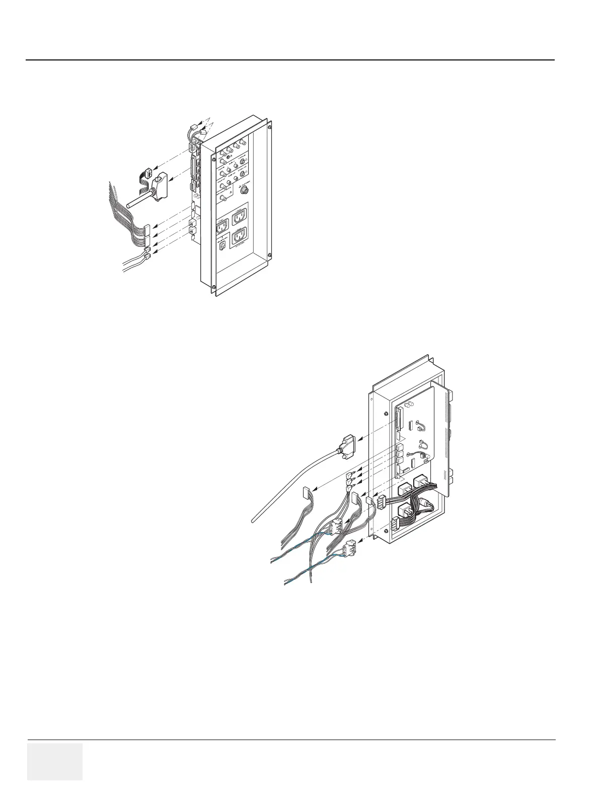
5.) Disconnect 8 connectors (1-8) from the left side of the Panel. Refer to Figure 8-74.
6.) Disconnect 9 connectors (9-17) from the right side of the Panel. Refer to Figure 8-75.
7.) Remove the Rear Panel Assy.
Figure 8-74 Disconnecting 8 Connectors
Figure 8-75 Disconnecting 9 connectors
1
CN1
4
5
6
7
8
2
1. External VGA Connector
2. Isolated Power Connector
3. Power Control Connector
4. Rear Digital Signal Connector
5. Main S/W and HDD LED Signal Connector
6. USB Down Stream Connector
7. InSite Connector
8. Ethernet Connector
3
9. Rear Analog Signal Connector
10. B/W Printer Power Connector
11. Line-In Connector
12. Line-Out Connetor
13. MIC In Connector
14. Sound Connector
15. Foot S/W Connector
16. Rear Panel Power-In Connector
17. Rear Panel Power-Out Connector
12
13
14
17
9
10
11
15
16
 Loading...


