GE MEDICAL SYSTEMS
D
IRECTION 2300000, REVISION 2 LOGIQ™5 SERVICE MANUAL
Chapter 8 Replacement Procedures 8-95
8-7-3-4 Removal Procedure (cont’d)
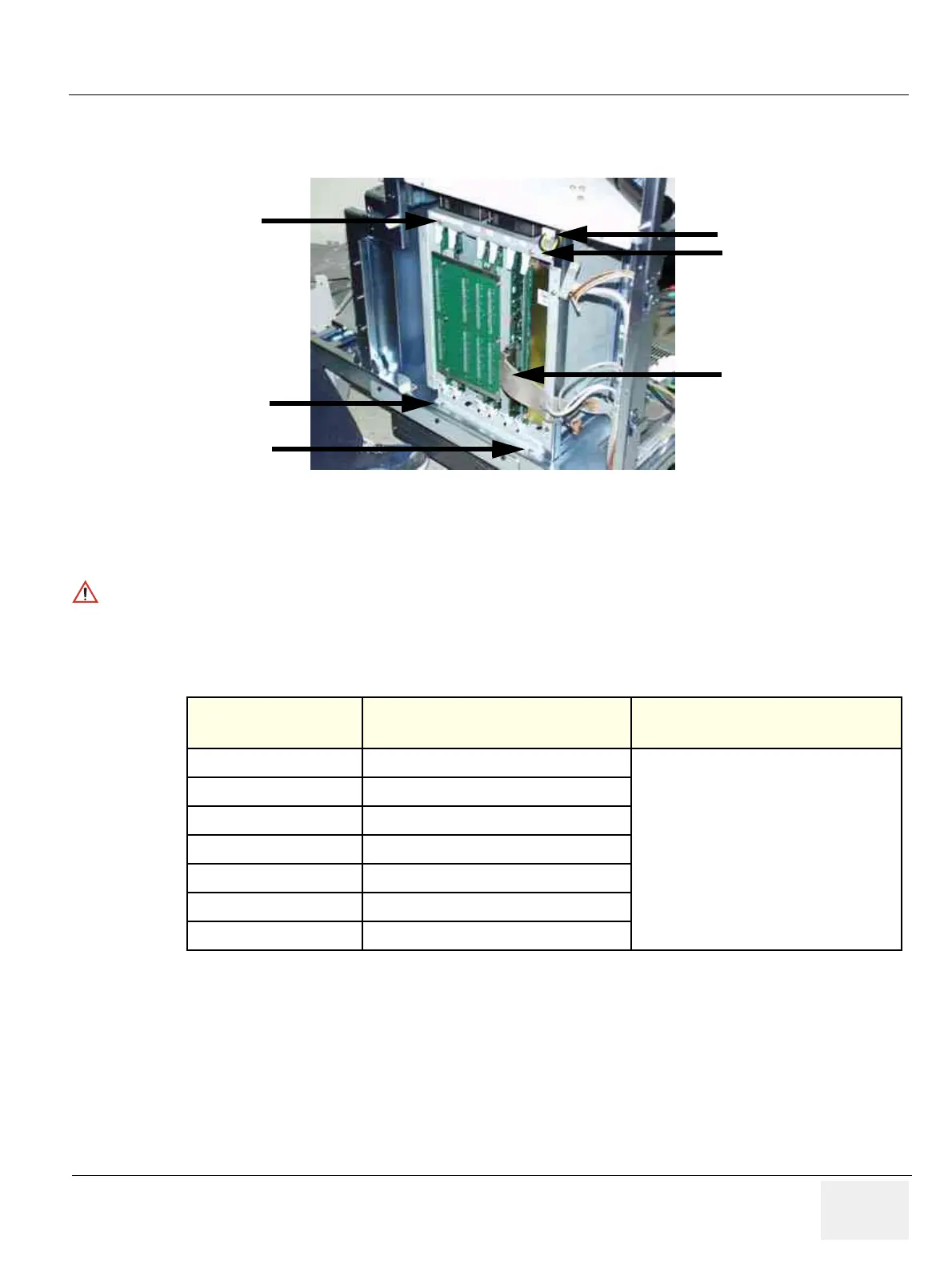
5.) From the right view, disconnect two connectors (9-10).
6.) Unscrew four (4) screws (11-14) to remove the Backplane Assy.
7.) Pull the Backplane assy out carefully.
8.) Perform the following functional tests. If all are successful, include the debrief script provided below.
8-7-3-5 Mounting Procedure
Install the new parts in the reverse order of removal.
Figure 8-94 Disconnect 2 connectors from the right
WARNINGWARNING
The weight of the Backplane with PCBs inside is approximately 20 kg. Two person is
needed in the next step.
Table 8-45 Functional Tests
Service Manual
Section Functional Test / Diagnostic Test Debrief Script
Section 4-3-1
Power On/Boot Up
“Service Manual, Direction
2300000, Rev 1+, Section 8-7-3. Equipment
passed all required tests and is ready for use. “
Section 4-3-2
Power Off / Shutdown
Section 4-9-8
Backplane Assy function check procedure
Section 4-3-4
System B/M-Mode Checks
Section 4-3-5
System CFM and PWD Checks
Section 10-5-2
Functional Checks (See Also Chapter 4)
Section 10-6
Using a Phantom
(9)
(10)
(11)
(12)
(13)
(14)