GE HEALTHCARE
DIRECTION 5245279, REVISION 3 LOGIQ™ P6/P6 PRO SERVICE MANUAL
Section 8-2 - DISASSEMBLY/RE-ASSEMBLY 8 - 77
8-2-32 RFC Assy
8-2-32-1 Tools
• Common philips screwdrivers
8-2-32-2 Preparations
• Shut down the system and switch off the main breaker.
8-2-32-3 Removal procedure
1.) Remove the Side Right Cover. Refer to the 8-2-14 "Right or Left Side Cover" on page 8-47.
2.) Remove the EMI Cover R. Refer to the 8-2-24 "EMI Cover L and R" on page 8-62.
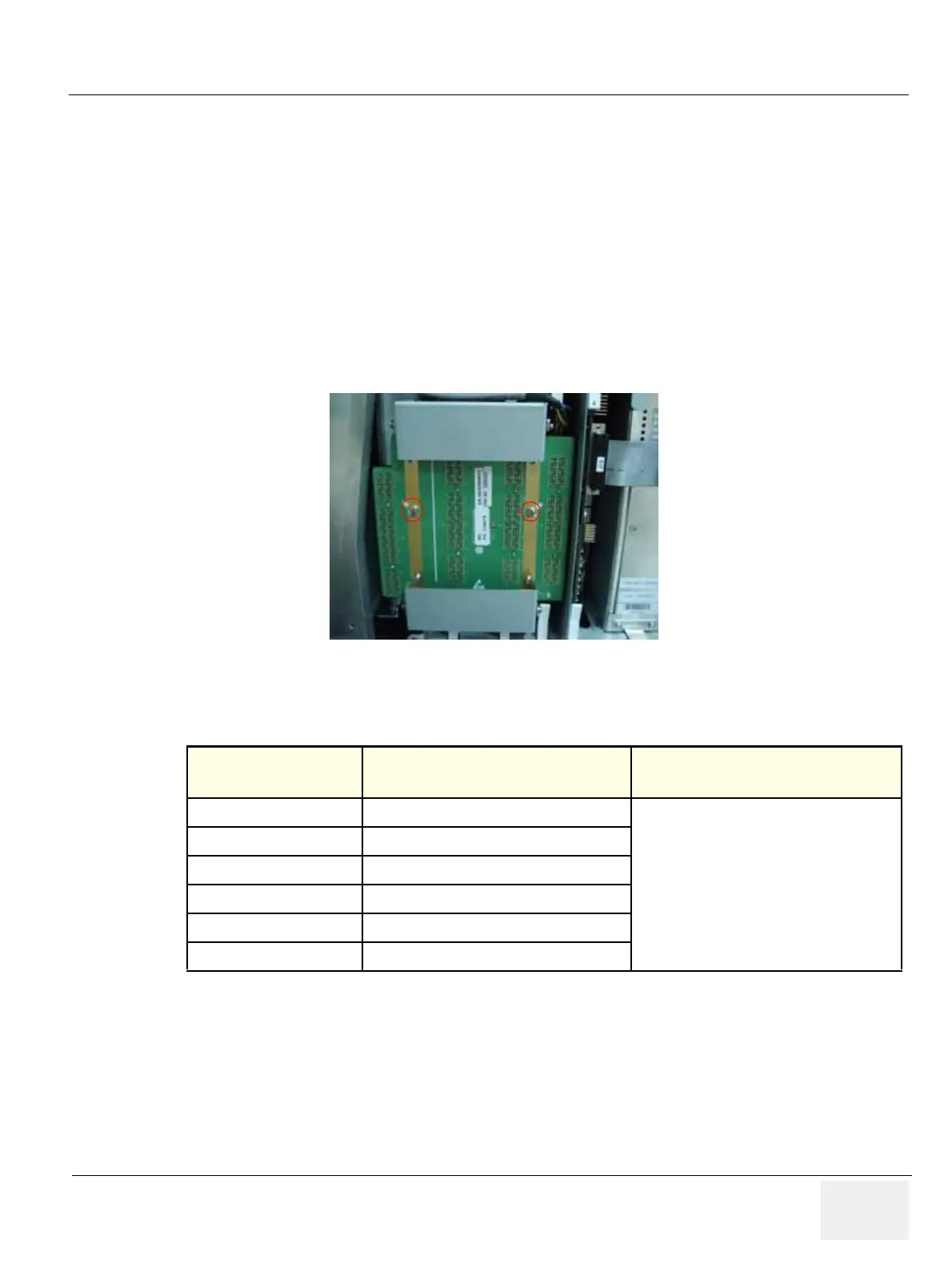
3.) Unscrew 2 screws (1,2) and eject the PCB. Refer to the Figure 8-118.
4.) Perform the following functional tests. If all are successful, include the debrief script provided below.
8-2-32-4 Mounting Procedure
Install the new parts in the reverse order of removal.
Figure 8-118 RFC Assy
Table 8-33 Functional Tests
Service Manual
Section
Functional Test / Diagnostic Test Debrief Script
Section 4-3-1
Power On/Boot Up
“Service Manual, Direction
5245279, Rev 3+, Section 8-2-32. Equipment
passed all required tests and is ready for use. “
Section 4-3-2
Power Off / Shutdown
Section 4-9-7
RFC Assy Function Validation Procedure
Section 4-3-4
System B/M-Mode Checks
Section 4-3-5
System CFM and PWD Checks
Section 10-5-2
Functional Checks (See Also Chapter 4)

 Loading...


